959
Basic I/O Unit Instructions Section 3-23
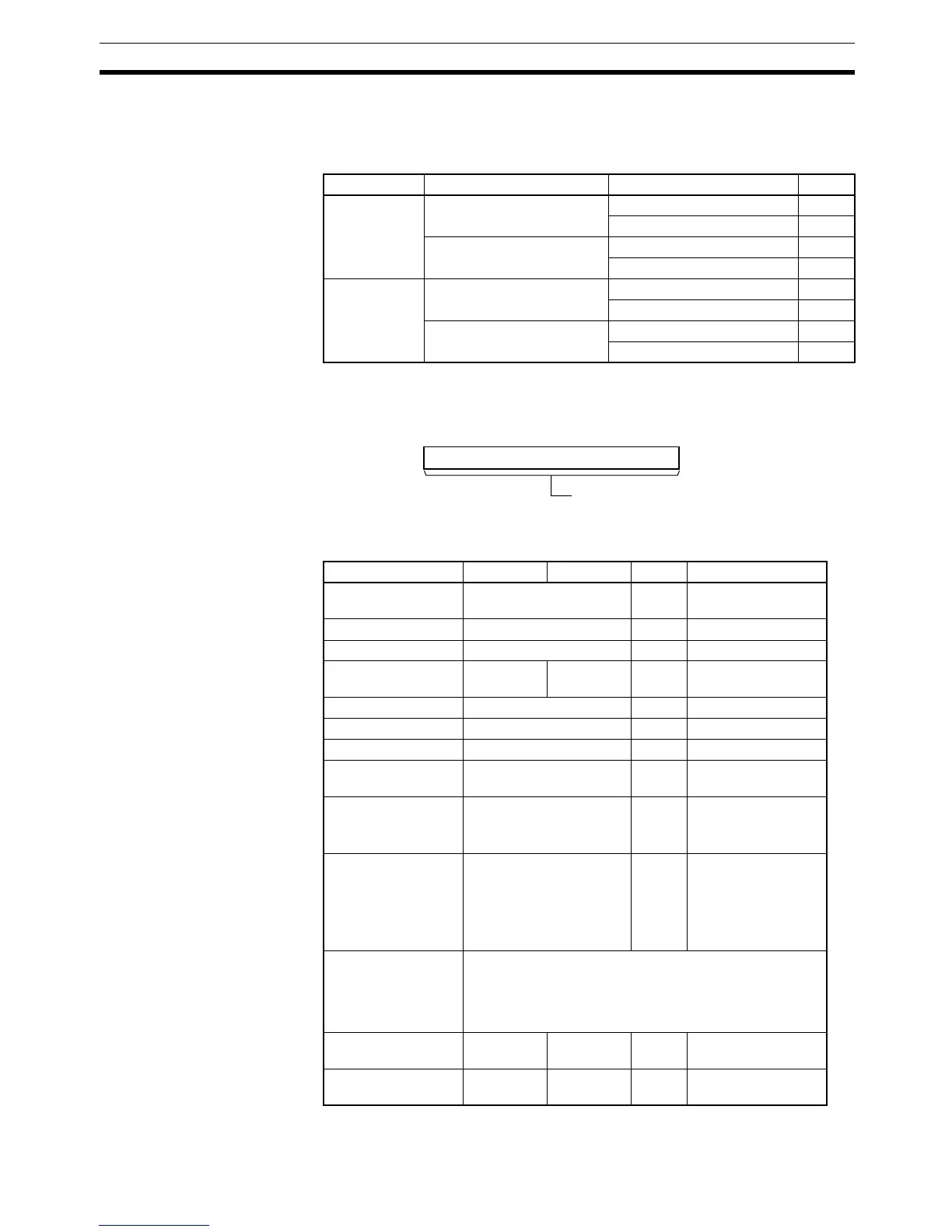
C: Control Data
The value of C indicates the number of digits of source data and the logic for
the Input and Output Units, as shown in the following table. (The logic refers to
the transistor output’s NPN or PNP logic.)
D: System Word
Specifies a work word used by the instruction. This word cannot be used in
any other application.
Operand Specifications
Source data Display’s data input logic Display’s latch input logic C
4 digits (S) Same as Output Unit Same as Output Unit 0000
Different from Output Unit 0001
Different from Output Unit Same as Output Unit 0002
Different from Output Unit 0003
8 digits
(S, S+1)
Same as Output Unit Same as Output Unit 0004
Different from Output Unit 0005
Different from Output Unit Same as Output Unit 0006
Different from Output Unit 0007
D
15 0
System word
(Cannot be accessed by the user.)
Area S O C D
CIO Area CIO 0000 to CIO 6143 --- CIO 0000 to
CIO 6143
Work Area W000 to W511 --- W000 to W511
Holding Bit Area H000 to H511 --- H000 to H511
Auxiliary Bit Area A000 to
A959
A448 to
A959
--- A448 to A959
Timer Area T0000 to T4095 --- T0000 to T4095
Counter Area C0000 to C4095 --- C0000 to C4095
DM Area D00000 to D32767 --- D00000 to D32767
EM Area without
bank
E00000 to E32767 --- E00000 to E32767
EM Area with bank En_00000 to En_32767
(n = 0 to C)
--- En_00000 to
En_32767
(n = 0 to C)
Indirect DM/EM
addresses in binary
@ D00000 to @ D32767
@ E00000 to @ E32767
@ En_00000 to @
En_32767
(n = 0 to C)
---
Indirect DM/EM
addresses in BCD
*D00000 to *D32767
*E00000 to *E32767
*En_00000 to *En_32767
(n = 0 to C)
Constants --- --- 0000 to
0007
---
Data Registers --- DR0 to
DR15
--- DR0 to DR15