The corresponding data settings screen appears in the Edit Pane. Configure the various set-
tings.
3 Create device variables.
Create device variables to access the FH/FHV
.
For details on how to create device variables, refer to Creating Device Variables in Sysmac
Studio Version 1 Operation Manual (Cat. No. W504).
4 Create and build a program to operate the device.
For details on how to create a program, refer to Programming in Sysmac Studio V
ersion 1
Operation Manual (Cat. No. W504).
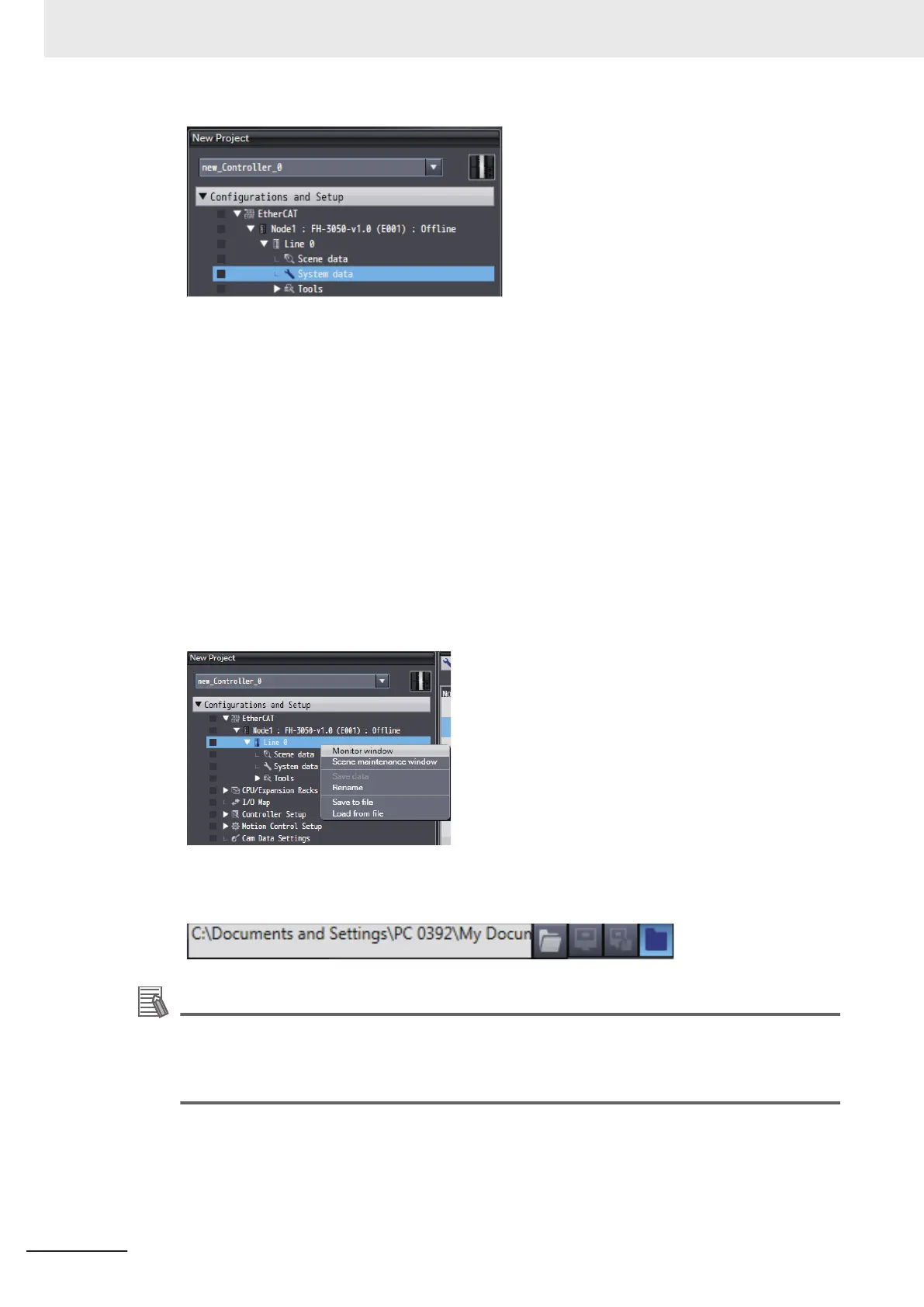
5 Open the scene monitor window.
Right-click FH/FHV
-XXXX - Line X in the network configuration editing pane and then select
Monitor window.
6 Specify the measurement image.
Click the image file selection button and then select an image.
Additional Information
There are no image files immediately after installation of the FH/FHV tool.
Acquire logged files or image files saved in the FH/FHV unit. T
o acquire images, refer to Saving
Logged Images in the Controller Memory (RAM) to a RAM Disk or an External Memory Device
in Vision System FH/FHV Series User's Manual (Cat. No. Z365).
7 Select Simulation - RUN.
The simulator starts.
When the simulator connection is complete, the simulator of the NJ/NX/NY
-series Controller
and FH/FHV vision sensor internally establish an online connection with EtherCAT and the
NJ/NX/NY-series Controller enters the operating state.
7 Offline Debugging
7 - 6
FH/FHV Series Vision System Operation Manual for Sysmac Studio (Z343-E1)

 Loading...

