A new processing unit can be added to the flow by dragging and dropping any processing unit in the
T
oolbox on to the list.
It is also possible to check the image that is the measurement target, and the measurement results for
each processing unit.
l
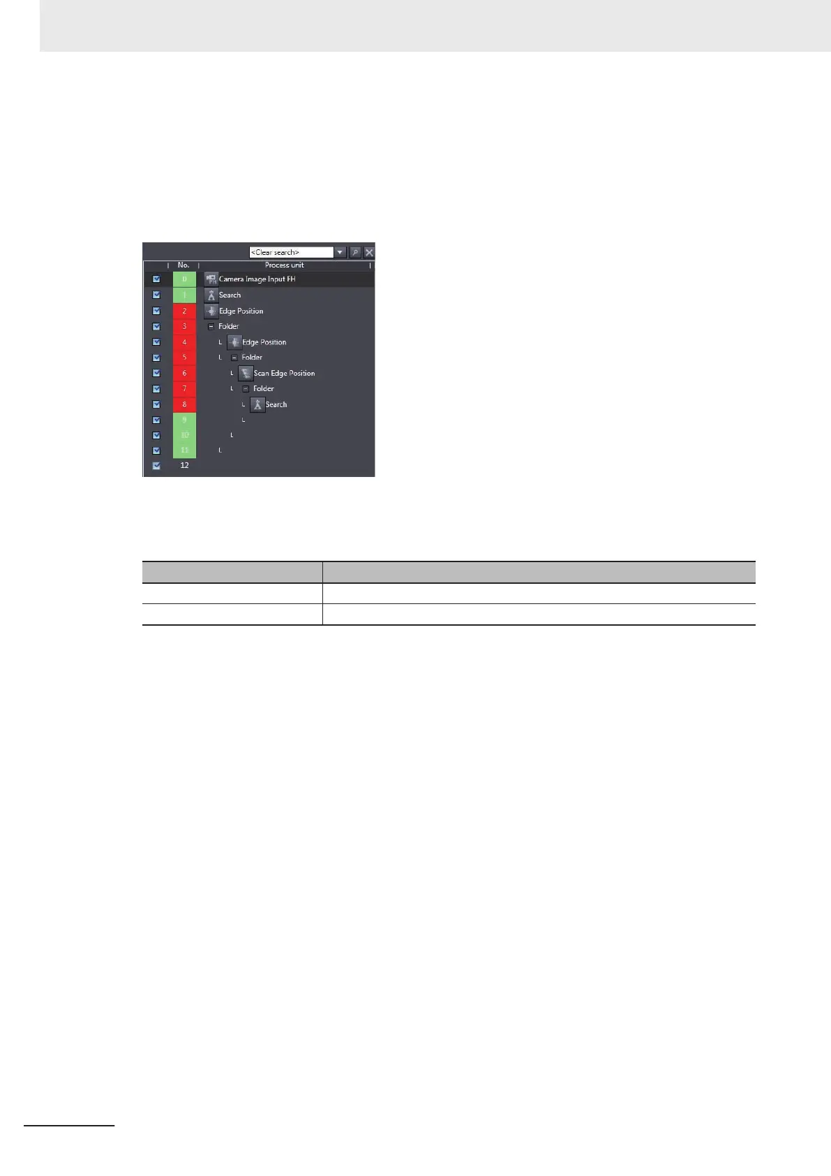
Flow display
This displays the processing flow for the relevant line or current scene.
Each editing process (adding, copying, deleting, etc.) of the processing units in the flow can be per-
formed.
Item Description
Search Searches for the specified processing unit from within the processing flow.
Flow list Displays the processing flow for the relevant line or current scene.
The registered processing units are displayed in the flow list.
With this tool, it is possible to select a processing unit to be used for measurement.
The measurements whose processing units with the checkmark removed will not be performed.
l
Data save
This saves the settings data to non-volatile memory of the FH/FHV sensor.
l
Transfer data
This transfers the settings for line 0 to line 1.
The button is displayed only when the operation mode is in Non-stop Adjustment Mode.
l
Non-stop data transfer
This transfers the settings for line 1 to line 0.
The button is displayed only when the operation mode is in Non-stop Adjustment Mode.
For details on T
ransfer data and Non-stop data transfer, refer to Setting the Operation Mode - Non-
stop Adjustment Mode in Vision System FH/FHV Series User's Manual (Cat. No. Z365).
l
Measure
Performs a single measurement.
The measurement process is performed for the image that is currently displayed.
2 Basic Operations
2 - 26
FH/FHV Series Vision System Operation Manual for Sysmac Studio (Z343-E1)

 Loading...

