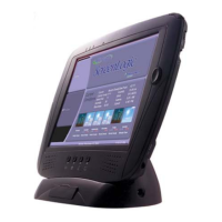
IntelliTouch
®
Control System User’s Guide
98
Section 5
Toubleshooting
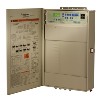
System Start-Up
The following information describes a basic system start-up procedure. Before switching on the power
to the IntelliTouch load center, rst afx the auxiliary relay labels to the appropriate buttons on the
Outdoor Control Panel. If necessary, write the function on the control panel.
Check Electronics
Check that the following plugs are seated correctly on the Personality board. For connector locations,
refer to the System Wiring Diagrams on page 107 and 108.
• Relay connectors - FLTRPUMP - AUX1-AUX8
• Temperature sensors connectors - WATER,SOLAR,AIR
• Transformer wire harness -J2
• Heater control connector -ELECHTRorscrewterminals
System Test
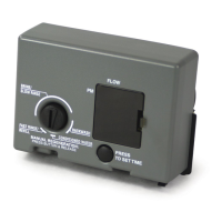
The following describes how to test the Outdoor Control Panel to activate the heater, valves and pumps.
This test assumes that all system equipment has been properly installed and connected to the Load
Center and Power Center.
Testing Valve Actuators and Pumps:
Use the following steps to test the valve actuators (CVA24T - P/N 263045) for proper rotation. For
Outdoor Control Panel System i5+3, i7+3, i9+3 (shared equipment).
To test the valve actuators and pump:
1. Power up the load center. Press the SYSTEMCONTROLbutton on the Outdoor Control Panel until
the SERVICELED light is on.
3. Press the V(Valve) button to select POOL.
4. Press the F (FilterPump) button to activate the lter pump. Water will be removed from the pool and
returned to the pool. The bypass valve will allow some water to fall from the spa back to the pool.
5. Set both valve actuators (CVA24T - P/N 263045) for suction and return. Use the toggle switch on
the rear of the CVA-24 to withdraw and return water from the pool.
Note: With the lter pump operating, if water is not being removed and returned to the pool, it may be
necessary to check the plugs on the Personality board and the toggle switches on the valve actuators.
Section 5
 Loading...