IntelliTouch
®
Control System User’s Guide
23
Section 3
Preparing the System for Initial Start-up
Setting up the IntelliTouch System
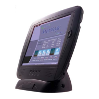
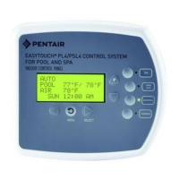
Use the following recommended steps to congure the IntelliTouch system using the Indoor Control
Panel or MobileTouch wireless controller.
1. Main screen preference settings (page 33)
Setup the Indoor Control Panel main screen. Set the system clock and what circuit names you wish to
display on the main screen.
2. Assign circuit names (pages 34-37)
Assign circuit names for output auxiliary equipment.
3. Creating custom names for auxiliary circuits (page 38)
There are twenty (20) user-dened circuit names available for identifying unique equipment (see page
38).
4. Assign a circuit function to a circuit name (page 79)
From your worksheet ProgrammableSettings section, assign circuit functions to all circuits that are
not marked GENERIC. Nothing needs to be done if the circuit is GENERIC (simple ON/OFF when the
button is pushed). From the CircuitFunctions screen, you can also assign special logic (IntelliBrite,
MagicStream, SAM, Floor Cleaner etc.) to a circuit by selecting one of the circuit functions. See page 41
for the complete list of circuit functions.
5. Create and assign a feature circuit name (page 79)
Review the temporary circuit names from the worksheet (page 89), create and assign circuit names to
the auxiliary (AUX) connections. On the AssignCircuitScreen, auxiliary circuit names are assigned
through Displays1through4. Displays 1 through 4 correspond to the main Load Center or Power
Center (Display 1) to which they are wired. Display 2 through 4 may be additional Expansion Centers.
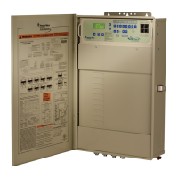
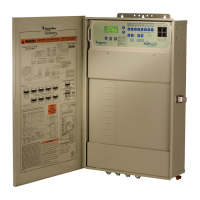
Note the original names presented, AUX1 through AUX10, correspond to the plug-in location of
the relay on the Outdoor Control Panel in the main Load Center or Power Center. Feature circuits are
assigned on the FeatureCircuit screen. Select from the available list circuit names. For a complete list
of circuit names see page 37. Up to 20 additional custom circuit names can may be custom created (see
page 38). For Macro circuits see page 80.
6. Configure valve actuators controlled by AUX or feature circuit (page 78)
Assign which circuits will activate which valves (A and B or optional C, D, E). If more than one circuit
must operate the same valve, then one Feature Circuit may be created and congured to activate the
valve. Then create Feature Circuits for all other circuits and use the Macro function to activate the valve
along with any relay connections.
 Loading...
