6
Workshop Manual, TPD 1377E, issue 4 73
100 Series
To remove and to fit Operation 6-9
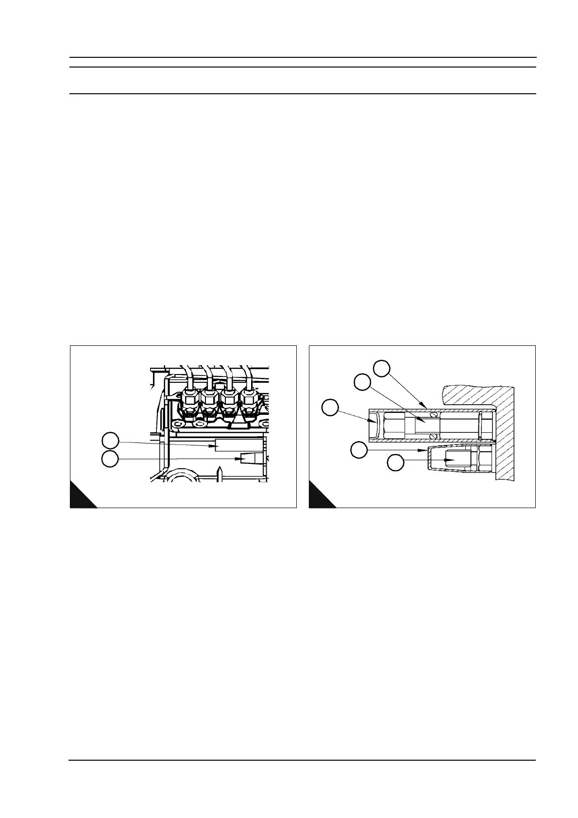
A requirement of emissions legislation is that access to adjustments (A1, A2) that affect the engine's exhaust
emissions is limited to personnel approved by Perkins Engines Company Ltd.
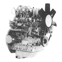
The fuel adjustment screw (B2) and maximum speed adjustment (B5) are affected. The fuel adjustment screw
has a tamper resistant body (B1) fitted over the screw and the maximum speed adjustment is protected by a
tamper evident plastic cap (B4).
To remove the tamper resistant body
1 Strike the tamper resistant device metal body (B1) with a suitable cold chisel approximately 10-15 mm from
the cylinder block flange. This will deform the body against the screw lock nut. This operation is necessary until
the metal tube cannot freely rotate around the fuel adjustment screw.
2 Rotate the metal body and the fuel adjustment screw together using a pair of pliers at the D-plug (B3) end
of the tube.
3 Remove the fuel adjustment screw (B2) as a single assembly completely from the cylinder block.
As the removal procedure for the original fuel adjustment screw and tamper resistant device body will cause
permanent damage to both these items, replacements must be obtained from PDC Irlam.
To re-fit a new fuel screw and service tamper resistant body
1 The fuel adjustment screw assembly (B2) may vary according to the engine build code. The appropriate
replacement must be obtained from PDC Irlam.
Continued
1
2
4
1
2
3
5
B
A
This document has been printed from SPI². Not for Resale