6
74 Workshop Manual, TPD 1377E, issue 4
100 Series
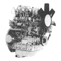
A special service version of the tamper evident body (D) must be fitted when a new fuel screw is fitted. A kit
part number U5MK0619 is available from PDC. This kit will be supplied only to permitted personnel and must
not be supplied to end users. A groove (D4) around the circumference of the tamper evident body is used to
identify it as a service part.
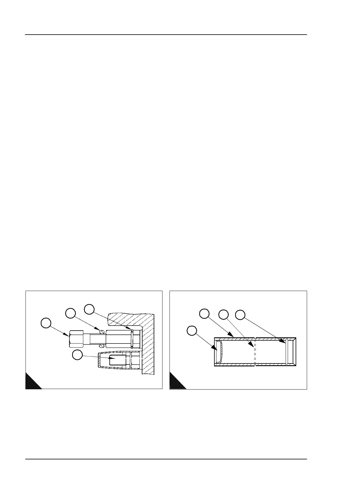
2 Fit the fuel adjustment screw assembly (C3) to the engine ensuring that there is a metal snap ring (C1)
located in the lock nut groove and a o-ring (C2) fitted.
3 On a suitable calibrated test facility, reset the engine performance parameters to the certified specification
indicated on the engine's emissions control information label mounted on the timing case.
4 Having set the full load fuel delivery to the certified specification and ensuring the lock nut is correctly
tightened, insert the D-plug (D2) into the service tamper resistant body (D3) at the opposite end of the internal
groove (D1). Fit the new service tamper resistant body assembly (D) over the fuel adjustment screw.
5 Tap on the tube until the internal groove (D1) in the body engages over the metal snap ring (C1) in the lock
nut.
To remove and re-fit the tamper evident maximum engine speed cap
The maximum speed adjustment has a plastic cap (B4) fitted by Perkins. The length of this fitted cap will be
either 22mm or 30mm in length depending on the original protrusion of the maximum speed adjustment screw
(B5). The cap is pressed by hand onto the adjustment screw and an internal lip locates into a groove on the
lock nut.
1 Remove the plastic cap (B4) from the maximum speed bolt (B5) with a suitable lever, taking care not to
damage the seal between the cylinder block and the locknut.
2 Make the necessary adjustment to maximum (no load) engine speed by rotating bolt clockwise to reduce
speed and anti-clockwise to increase speed with the engine throttle lever fully open.
Note: The only permitted adjustment to the maximum engine speed is to correct the speed in accordance with
the high idle speed shown on the emissions compliance label mounted on the engine timing case.
3 After adjustment to within the certified maximum speed range, a new service cap of the appropriate length
can be obtained from PDC Irlam. The replacement service cap will be red in colour part number 131276440 -
30mm length or 131276450 - 22 mm length. This cap will be supplied only to permitted personnel and must
not be supplied to end users.
4 Hand press the replacement service cap onto maximum speed bolt (C4) lock nut.
A warranty claim will not be accepted if it can be seen that an adjustment to the maximum engine speed setting
(B5) or the fuel adjustment screw (B2) has been made by personnel not approved by Perkins.
1
2
3
4
c
C
D
2
3
4
1
This document has been printed from SPI². Not for Resale