THE NEW PIPER AIRCRAFT, INC.
PA-32-301FT / 301XTC
MAINTENANCE MANUAL
PAGE 12
Jun 1/03
5G12
81-20-00
C. Adjustment (See Figures 2 and 3.)
The exhaust wastegate (butterfly) valve is mechanically linked to a hydraulically-driven servo by the
wastegate actuator rod. The butterfly valve/actuator rod orientation is set at the factory, but may
occasionally require adjustment in the field.
(1) Remove the engine cowling as described in 71-10-00.
CAUTION
: IF LOCKWIRE ON V-BAND COUPLING IS FOUND BROKEN, CLOSELY
INSPECT V-BAND T-BOLT FOR STRETCHING, CRACKING, OR OTHER
DAMAGE BEFORE REUSING THAT V-BAND COUPLING.
CA
UTION: WHEN REMOVING OR INSTALLING V-BAND COUPLINGS, SLIDE COUPLING
OVER THE END OF THE PIPE BEFORE ASSEMBLY/ DISASSEMBLY.
EXCESSIVE SPREADING CAN LEAD TO PREMATURE COUPLING FAILURE.
(2) Remove the V-band coupling securing the tailpipe assembly to the wastegate and separate
wastegate and tailpipe assembly sufficiently to allow access to the butterfly valve within the
wastegate.
(3) Place the shank end of a #20 drill bit between the inner wall of the wastegate assembly and
the butterfly valve (Refer to Figure 3.)
(4) A slight drag should be felt when the drill bit is moved in and out. If the drill bit is too loose,
adjust the actuator rod end to obtain the proper clearance.
(5) Place the tailpipe assembly in position and secure with the appropriate V-band couplings.
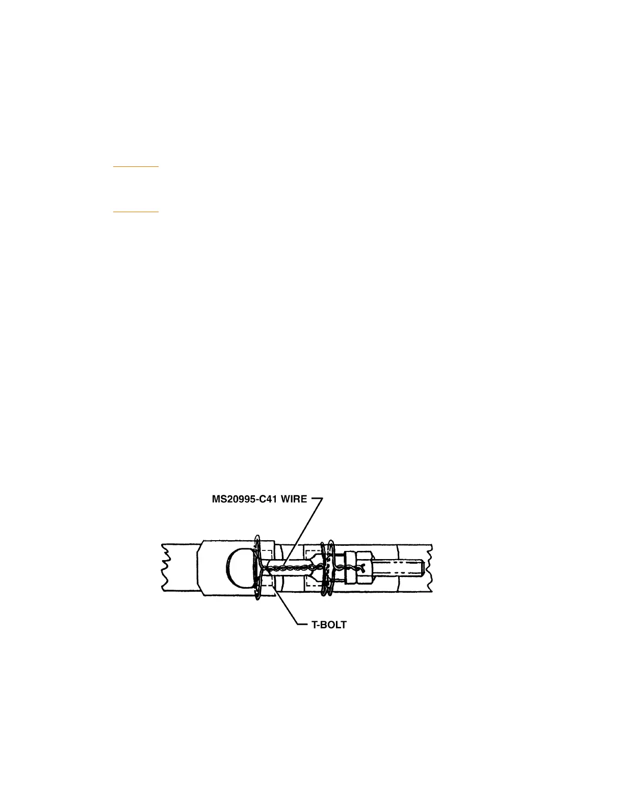
Lockwire couplings as shown in Figure 4.
(6) Install upper and lower cowling as described in 71-10-00.
(7) Flight test the aircraft to determine critical altitude (12,000 feet minimum) at MAX power of
2500 RPM and 38 inches Hg.
(8) If the above criteria is not met, see Chart 1.
Lockwiring V-Band Couplings
Figure 4