THE NEW PIPER AIRCRAFT, INC.
PA-32-301FT / 301XTC
MAINTENANCE MANUAL
PAGE 5
Jun 1/03
5C11
74-10-00
B. Removal
CAUTION: ASCERTAIN THAT THE PRIMARY CIRCUIT OF THE ENGINE IS GROUNDED
BEFORE WORKING ON THE ENGINE.
Before removing the magnetos, make sure the magneto switches are OFF.
WARNING: THE MAGNETO IS NOT INTERNALLY GROUNDED, WHEN THE GROUND LEAD IS
DISCONNECTED THE MAGNETO IS HOT. REMOVING THE HARNESS ASSEMBLY
FIRST AND INSTALLING THEM LAST, MINIMIZES THE DANGER OF STARTING
THE ENGINE ACCIDENTALLY WHEN THE GROUND LEAD IS REMOVED FROM
THE MAGNETO.
(1) Turn the engine crankshaft in the normal direction of rotation until the No. 1 cylinder is in the
full-advance firing position.
(2) Remove the harness cap from the magneto. Before doing this, place an index mark on the
harness cap and distributor housing to ensure proper alignment upon reassembly.
(3) Disconnect the P-lead and pressurization tube from magneto.
(4) Remove the nuts, washers and clamps, and remove the magnetos from the engine.
(5) Cover the magneto accessory opening with suitable material to prevent internal engine
contamination.
C. 500 Hour Inspection and Cleaning
Each 500 hours, remove magneto per paragraph B, above, and disassemble magneto, as
necessary, per procedures in paragraph D, below. Inspect and clean magneto as follows:
(1) Inspect ball bearing assembly by rotating rotor shaft. Shaft should rotate freely without binding
or sticking, but should not appear loose. If not, replace bearings.
(2) Inspect rotor for damage or worn keyway. Check rotor surfaces for wear.
(a) Inspect oil seal location on shaft.
(b) Assemble bearings and rotor per paragraph E (1) & (2), below.
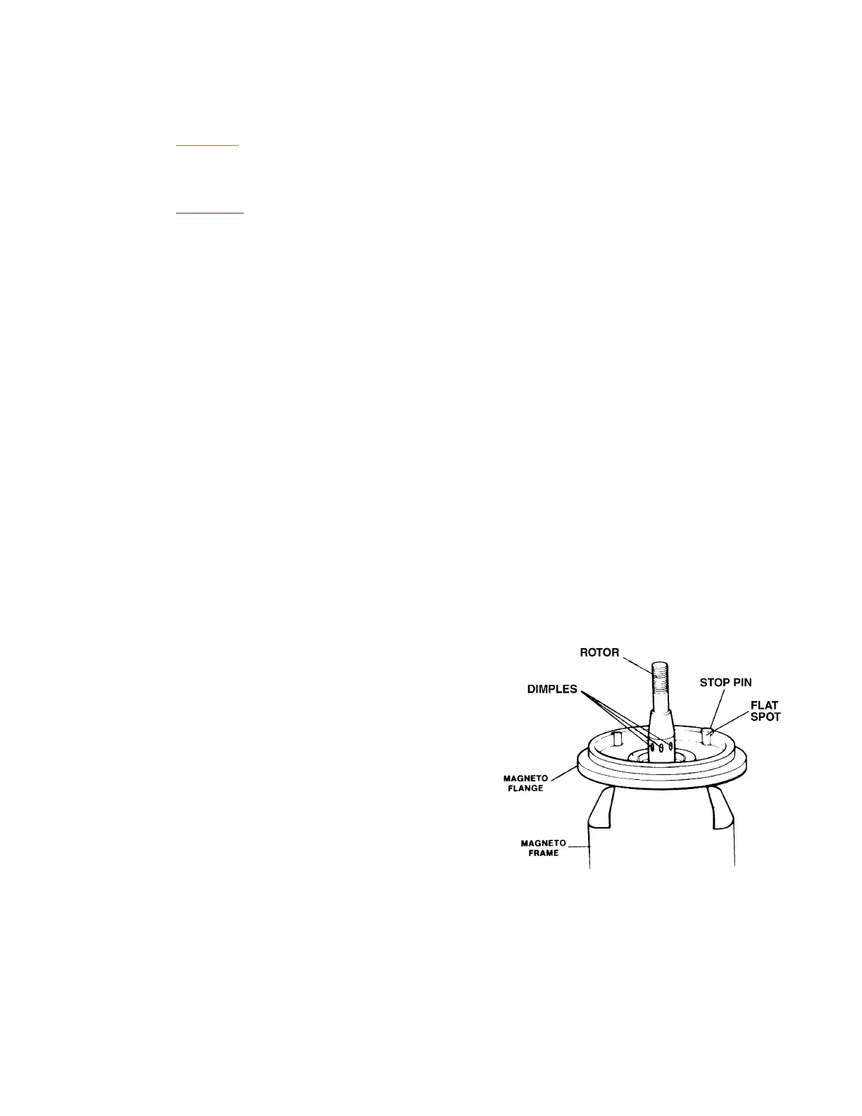
(c) In the left magnetos only (i.e. - impulse
coupled), inspect magneto rotor shaft
at impulse coupling (see Figure 2). If
the heel of the pawl has struck the
shaft and caused the shaft to dimple in
excess of .006 inch per side, the rotor
shaft must be replaced.
(3) In the left magnetos only (i.e. - impulse
coupled), clean and inspect the impulse
coupling:
(a) Clean to bare metal to ensure a
reliable inspection. Use a suitable
degreasing solvent to remove all oil or
sludge buildups.
(b) Inspect impulse coupling shell and hub
for cracks, rust or corrosion. Replace
impulse coupling, if found.
(c) Inspect hub shaft and keyway for
deformation or damage. Replace
impulse coupling, if found.
Rotor and Stop Pin
Figure 2