THE NEW PIPER AIRCRAFT, INC.
PA-32-301FT / 301XTC
MAINTENANCE MANUAL
PAGE 3
Jun 1/03
3D9
28-40-00
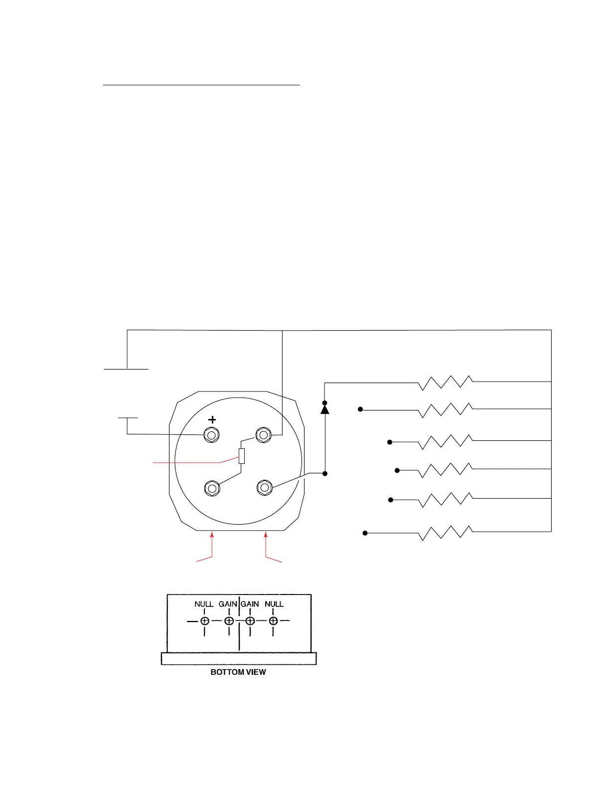
2. Fuel Quantity Gauge Bench
T
est/Adjustment (Refer to Figure 3.)
A. Install 5 ohm dummy resistor across sender terminal not to be tested as shown.
B. Connect resistance decade across sender terminal to be tested as shown.
C. Connect power supply as shown and adjust to provide 24 to 28 Vdc.
D. Low End Adjustment
Select posistion “F” on resistance decade. Verify that instrument needle points to “0”. If not, adjust
respective “NULL” potentiometer to center needle on “0” radial.
E. High End Adjustment
Select posistion “A” on resistance decade. Verify that instrument needle points to “F”. If not, adjust
respective “GAIN” potentiometer to center needle on “F” radial.
F. Full Range Check
After low and high end adjustments have been made, verify that for each resistance value, the
gauge indication is as shown in Chart 2.
Fuel Quantity Gauge Bench Test/Adjust Set-Up
Figure 3