THE NEW PIPER AIRCRAFT, INC.
PA-32-301FT / 301XTC
MAINTENANCE MANUAL
PAGE 25
Jun 1/03
2D13
21-50-00
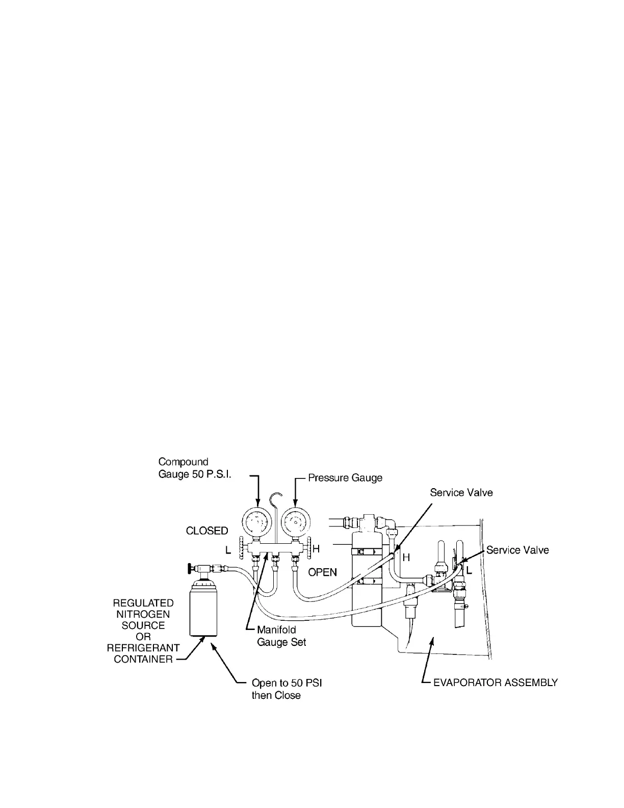
Leak Test Hookup
Figure 8
(2) Leak Detection (refer to Figure 8.)
(a) Close both the low side and high side valves on manifold hand set.
(b) Connect manifold hand set middle port (yellow) hose to a regulated (0-300 psig) gaseous
dry nitrogen source or a container of HFC-134a refrigerant.
(c) Open nitrogen source or refrigerant container service valve.
(d) Open the manifold hand set high side valve until a pressure of 50 psig is reached on low
side gauge. Close high side valve.
(e) Locate leak(s) using soap and water in a thick solution; or, if using HFC-134a, an
electronic leak detector designed to detect HFC134a refrigerant can also be used.
(f) Tighten/re-tighten fittings as necessary to stop leak(s). If leaks are due to damaged or
worn components, proceed with refrigerant recovery/system discharge, perform repairs or
component replacement and repeat leak detection procedure.
(g) Check that the both high side and low side valves on the manifold hand set are closed.
(h) Close service valve on nitrogen source or refrigerant container. Disconnect yellow
manifold hand set center hose from nitrogen source or refrigerant container.
(i) On systems equipped with quick disconnect connections, close coupler valves.
Disconnect manifold hand set red and blue hoses from airplane service ports. Remove
manifold hand set.
(j) If HFC-134a refrigerant was used, recover remaining refrigerant from system using the
Robinair 34700 (or other approved) charging station (see paragraph 3.C). Any quantity of
oil recovered from aircraft must be measured and an equal amount of new oil (i.e. - PAG
with HFC134a) must be added to system before recharging.
(k) When refrigerant recovery is complete, on systems equipped with quick disconnect
connections, close coupler valves. Disconnect charging/test station from service ports.
(l) Evacuate the system, see below or paragraph 3.C.
(m) Immediately charge the system, see below or paragraph 3.C.