THE NEW PIPER AIRCRAFT, INC.
PA-32-301FT / 301XTC
MAINTENANCE MANUAL
PAGE 16
Jun 1/03
2G16
24-30-00
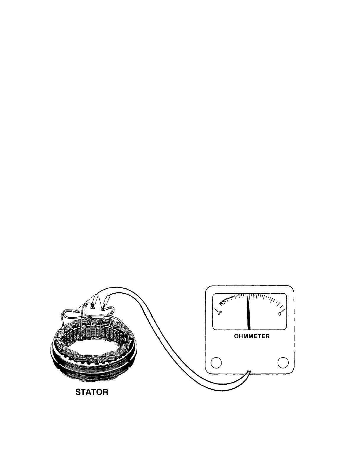
(5) Stator Continuity Test (Refer to Figure 15.)
(a) Using a 100 watt soldering iron, disconnect the three stator wires from diode assembly,
and remove stator from rear housing.
(b) Set the ohmmeter selector switch on resistance scale 1 and zero the meter.
(c) Connect ohmmeter leads alternately between all three sets of leads. Meter readings
should be equal between any pair of stator leads.
(d) If unequal readings are obtained, the stator winding is open. Check wiring junction. If
breaks are found repair and recheck. If unequal readings still exist, replace the stator.
(6) Stator Ground Test (Refer to Figure 16.)
(a) Set ohmmeter selector switch on resistance scale 1000 and zero the meter.
(b) Connect one meter lead to bare metal portion of stator core and other lead alternately to
each of the stator leads. The ohmmeter should read infinity (no needle movement). Be
sure lead is making good contact with stator core surface.
(c) If meter shows any reading (needle moves) the stator is grounded and must be replaced.
(7) Diode Testing (Refer to Figure 17.)
Stator must be disconnected from rectifier assembly to perform this test. Rectifier shown
removed for clarity.
(a) Set the ohmmeter selector on resistance scale 10 and zero the meter.
(b) Test the negative diodes by connecting one ohmmeter lead to GRD post terminal on
rectifier and connect other lead to each stator lead connection of rectifier momentarily.
Reverse ohmmeter leads and check in opposite direction. Meter must shown continuity in
one direction and infinity (no needle movement) in other direction.
Stator Continuity Test
Figure 15