(5) The brush and holder assembly (5) is installed in a cavity inside the rear housing. The brushes
ride the surfaces of the slip rings on the rotor shaft under spring pressure and transmit field
current through their circuit to ground. One brush or field terminal is, therefore, insulated from
the housing.
(6) The rectifier assembly is located between the stator and the inside surface of the rear housing.
Attachment to the housing is made by means of mounting studs that protrude from the positive
and negative diode plates (heat sinks). The positive plate is insulated from the housing, and
the negative plate is grounded to the housing through the studs. The rectifier assembly has a
printed circuit board spaced away from the heat sinks. (Refer to Figure 4.)
The stator winding leads (6) are soldered to integral terminals on the back of the circuit board.
The stator phase top is attached to the insulated stator terminal. The heat sinks are attached to
the circuit board with insulated spacers and roll pins maintaining the necessary separation
between the two assemblies. The diodes themselves are exposed. The rectifier assembly has
three diode plates connected to an AC potential. Each of the three plates is connected to one
of the three stator leads. Two steel conductor plates or “bus bars”, one positive and the other
negative, circle the diodes beginning at the BAT and GND terminal studs. The bus bars act as
termination points for collecting the DC current from the terminal wire of each diode. One
positive and one negative diode is soldered to each of three stamped aluminum plates to form
the plate and diode assemblies. The aluminum plates serve as heat sinks to cool the diodes by
providing increased surface area to the air flow through vent slots in the rear housing to the fan
at the front of the alternator.
One plate and diode assembly is connected to each of the three leads to form the full wave
bridge rectifier. Diode terminal wires are connected to the bus bars by means of a flexible
connector wire. One diode is connected to the positive bus bar, and the other diode, on each
plate, is connected to the grounded or negative bus bar. (Refer to Figure 5.)
THE NEW PIPER AIRCRAFT, INC.
PA-32-301FT / 301XTC
MAINTENANCE MANUAL
PAGE 2
Jun 1/03
2G2
24-30-00
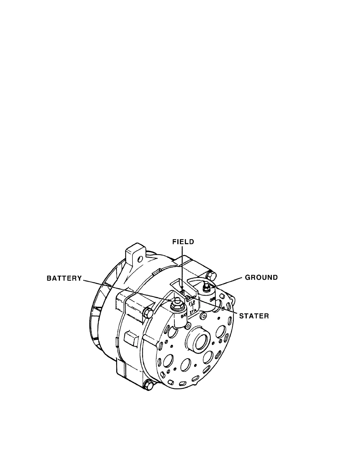
Rear View and Terminal Identification
Figure 2