n
av
Average motor speed [min
-1
]
n
1
... n
n
Motor speed [min
-1
]
t
1
... t
n
Duty cycle [s]
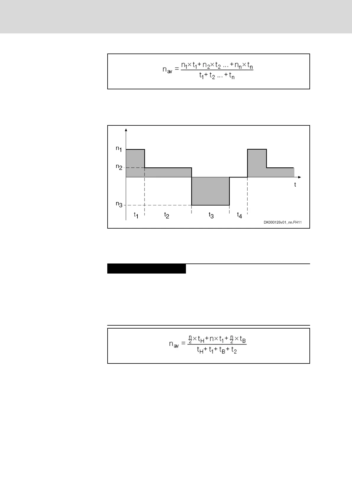
Fig.15-2: Average Speed; Effects of Run-Up and Braking Times not Taken Into
Account
Fig.15-3: Speed Characteristic; Effects of Run-Up and Braking Times not Taken
Into Account
In dynamic applications with short cycle times, e.g. roll feeds and nibbling
machines, run-up and braking times must be taken into account.
Damage to the drive controller!
● The DC bus capacitors in the drive controller have been dimensioned
for loading with continuous power.
● If loaded with cyclic charging and discharging processes of high energy
content, the DC bus capacitors can be overloaded, especially with de‐
creasing mains connection voltage.
Operate additional capacitors at the DC bus.
Average Speed With Run-Up and
Braking Times Taken Into Account
n
av
Average motor speed [min
-1
]
n
Motor speed [min
-1
]
t Time [s]
t
H
Run-up time [s]
t
B
Braking time [s]
Fig.15-4: Average Speed; Effects of Run-Up and Braking Times Taken Into Ac‐
count
Bosch Rexroth AG DOK-INDRV*-SYSTEM*****-PR06-EN-P
Rexroth IndraDrive Drive Systems with HMV01/02 HMS01/02, HMD01, HCS02/03
248/309
Calculations