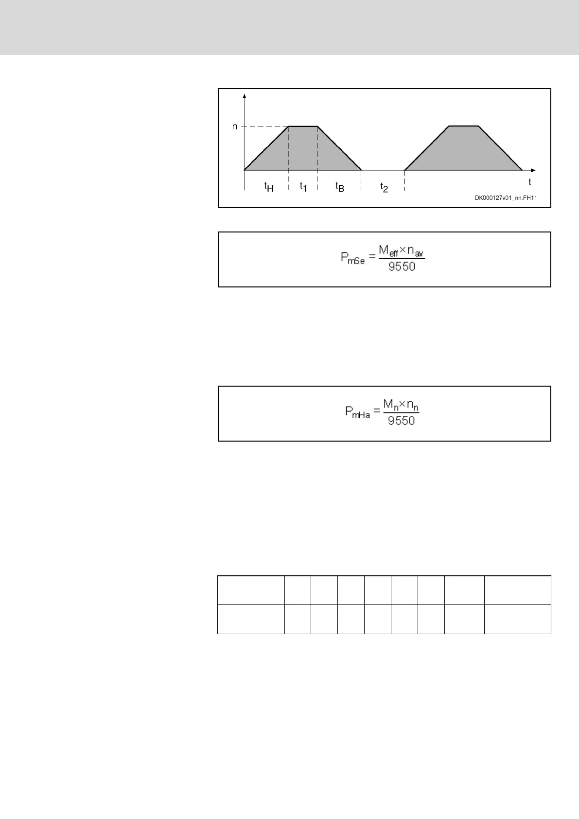
Fig.15-5: Average Speed; Effects of Run-Up and Braking Times Taken Into Ac‐
count
Mechanical Power for Servo
Drives
P
mSe
Mechanical continuous power for servo drives [kW]
M
rms
Effective motor torque [Nm]
n
av
Average motor speed [min
-1
]
Fig.15-6: Mechanical Power for Servo Drives
Mechanical Power for Main Drives
Main drives are drives which are mainly used in the constant power speed
range. Thus, nominal power is decisive for sizing the mains supply. The me‐
chanical nominal power of the main drives can be taken from the operating
characteristic or calculated from nominal speed and nominal torque.
P
mHa
Mechanical nominal power for main drives (shaft output) [kW]
M
n
Nominal motor torque [Nm]
n
n
Nominal motor speed [min
-1
]
Fig.15-7: Mechanical Power for Main Drives
DC Bus Continuous Power for
Servo Drives
The drive controller or the group of drive controllers has to make available the
DC bus power. However, in most applications, simultaneous loading of all
drives will not occur; thus, only the simultaneously occurring power must be
considered for calculating the DC bus continuous power to be made available
for servo drives. To calculate the DC bus continuous power to be made avail‐
able for typical NC feed axes at machine tools, inclusion of a so-called simul‐
taneity factor has proved to be favorable in practical application:
Number of ax‐
es
1 2 3 4 5 6 7 n = n + 1
Simultaneity
factor (F
G
)
1 1,15 1,32 1,75 2,0 2,25
F
G
=2,5 F
Gn
= F
G
+ 0,25
Tab.15-1: Simultaneity Factors
DOK-INDRV*-SYSTEM*****-PR06-EN-P
Rexroth IndraDrive Drive Systems with HMV01/02 HMS01/02, HMD01, HCS02/03
Bosch Rexroth AG 249/309
Calculations