A
Angela BarberAug 26, 2025
What to do if Riele Measuring Instruments shows + 15 V out of range DC?
- JjohnsonryanAug 27, 2025
If the Riele Measuring Instruments indicates that + 15 V is out of range DC, check the voltage (SM chapter 4.3).
What to do if Riele Measuring Instruments shows + 15 V out of range DC?
If the Riele Measuring Instruments indicates that + 15 V is out of range DC, check the voltage (SM chapter 4.3).
What to do if Riele Measuring Instruments shows + 5 V out of range DC?
If the Riele Measuring Instruments indicates that + 5 V is out of range DC, check the voltage (SM chapter 4.40).
What to do if Riele Measuring Instruments shows +/- 12 V out of range DC?
If the Riele Measuring Instruments indicates that +/- 12 V is out of range DC, check the voltage (SM chapter 4.40).
Technical product management and support contact details for ROBERT RIELE GmbH & Co KG.
Instrument construction complies with EN standards; user must follow manual for safe operation.
Electrical equipment hazards, sample handling caution, and general safety precautions.
Design for simple error detection and module exchange; fast repair on service level A.
Warranty periods for instruments and spare parts, handling of warranty claims, and important information.
Warranty void for improper use, unauthorized modifications, damages, etc.
Repairs by authorized personnel; Return Authorization procedure for parts marked "R".
How to access and use mode functions for basic settings during a method course.
Procedure for selecting and executing utility programs for instrument functions.
How to access service tools, protected by a password, for instrument parameter adjustments.
Resets instrument parameters to default values, ends with a beep and program release printout.
Deletes user-edited methods; caution advised for data backup before proceeding.
Deletes extended memory for nonlinear methods and user-defined methods.
Displays and allows entry of the instrument's serial number.
Extends measurement time for low light gain at small wavelengths.
Allows assignment of filter positions and entering new wavelengths.
Enables continuous measuring mode based on calculation procedure.
Submenu for eight temperature-related functions, including regulation and calibration.
Switches temperature regulation on or off and selects temperature levels.
Displays and allows correction of temperature regulation by changing temperature setting.
Displays and allows correction of temperature regulation by changing temperature setting.
Calibrates temperature regulation by inputting measured temperature from external system.
Displays required and actual temperature values and cuvette adapter type.
Displays counter value of temperature ADC and current stability value.
Checks correct storing of user-defined methods by determining the BCC of a method.
Displays and adjusts the correction value of the analog-digital converter.
Displays actual voltages on the PCB, listing various voltage points.
Reduces the voltage of the halogen lamp for adjustment in vertical direction.
Reads and sets the PCB layout attribut, which may affect software applications.
Clears the memory of the patients data management system.
How to equip the filter wheel with additional filters and update wavelengths via service routine.
Procedures for filter wheel replacement using specialized tools.
Lists specific voltage checks and measurement points on the motherboard.
Instructions for checking and adjusting the 12 VDC halogen lamp voltage.
Lists protection and specification details for fuses F1, F2, and F3.
Explains the conversion of photocurrent to voltage and ADC value, including offset.
Procedure for adjusting the amplifier stage, amplification, and offset.
Continues the procedure for checking sensitivity levels and AD-transducer values.
Instructions for checking and adjusting the contrast of the LCD display.
General description of temperature control, its components, and microcontroller system.
Details cooling levels, Peltier element operation, and temperature sensor voltage signals.
Explains the PID-controller algorithm and the process for thermal adjustment.
Steps to perform after changing the motherboard, including checks and adjustments.
Lists commands for controlling device functions, software version, dark adjustment, and multiplexer level.
Lists commands for method strings, filter positions, printer control, and temperature settings.
Lists commands for temperature values, control, stability, and system status.
Lists commands for PCB layout version, laboratory name, and user name settings.
Describes the procedure for calibrating cuvette temperature by comparing true vs. set temperature.
Explains temperature measurement using a thermistor-probe and DMM.
Specifies room temperature, humidity, and ventilation requirements for calibration.
Step-by-step guide for using cuvette adaptors, DMM, and software for calibration.
Table mapping resistance values to temperatures for the thermistor.
Explains how to calculate assigned temperature using linear interpolation from resistance values.
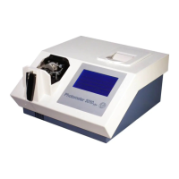
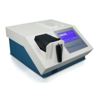
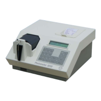
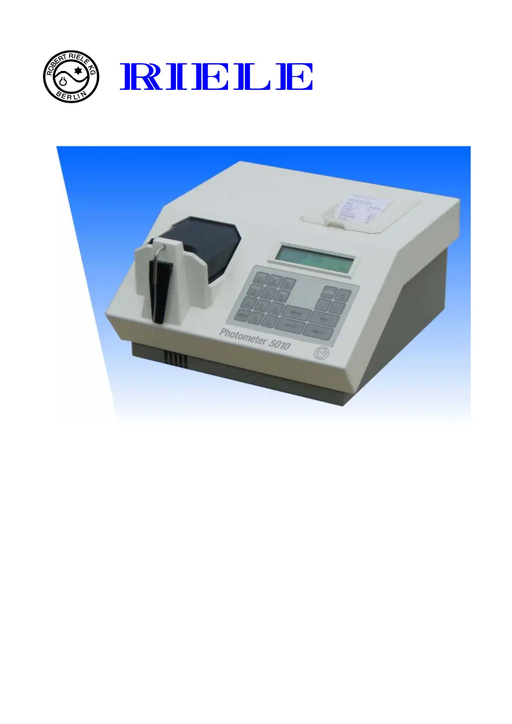
| Brand | Riele |
|---|---|
| Model | Photometer 5010 |
| Category | Measuring Instruments |
| Language | English |