Reference Manual Rev 1.13
004R-646-113 Page 17
proper sealing procedures be adhered to. Refer to Trade Label page 115, Lead
Seals page 115, Destructible Sticker Seals page 115 and Electronic Seal page 115
sections for more information.
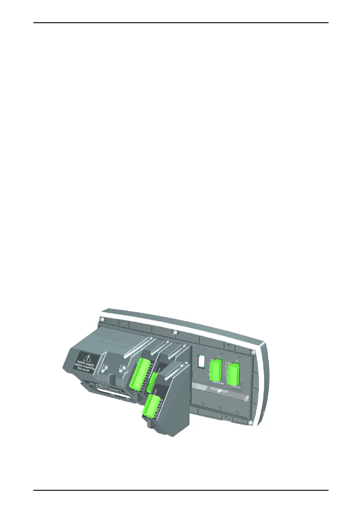
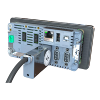
3.13. Accessory Module connection
Up to 4 accessory modules can be plugged into the rear of the instrument. There
are many types of modules which can be used. These modules provide additional
features such as:
power supply options, e.g. mains power or batteries
communications ports, e.g. Ethernet or RS485 networking
digital inputs and digital outputs, e.g. external buttons or setpoint outputs
expanded memory, e.g. DSD functionality.
Caution: Instrument should be switched off before connecting or disconnecting
accessory modules.
Each module will come with a manual which explains the features, installation and
use of the module.
After connection, the module needs to be configured using the instrument setup
menus. All hardware test functions and hardware options (such as serial baud rates
or digital input debouncing) are in the H.WARE (hardware) menu described in
section 0 page 59. Module resources (such as digital inputs or serial ports) are
assigned in specific function menus. For example, the output used by a particular
setpoint is set in the setpoint menu.
Note: Power supply options can only be connected in the left position. Other
modules can be connected in any position.