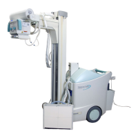
Mobile DaRt Operation Manual
11
Contents
Chapter 1 Introduction
Introduction 1-2
Chapter 2 Outline
2.1 Purpose 2-2
2.2 Features
2-2
2.3 Use Conditions
2-4
2.3.1 Environmental Conditions
2-4
2.3.2 EMC (Electro-Magnetic Compatibility)
2-5
2.4 Conformity to IEC Standards
2-6
2.5 Classification of Equipment
2-7
2.6 Safety Symbols for System 2-8
Chapter 3 Descriptions of Each Part
3.1 Outside View 3-2
3.2 X-ray Control Panel
3-3
3.3 Power Supply Panel
3-6
3.4 Touch Panel Monitor
3-8
3.5 Hand Switch
3-9
3.6 Driving Handle Section
3-10
3.7 X-ray Tube Operating Section and Collimator
3-11
3.8 Operation Handle
3-13
3.9 Tube Arm Joint Section
3-14
3.10 Main Circuit Breaker and Additional Protective Electrical Earthing Wire 3-15
3.11 CXDI-50G Imaging Unit
3-17
3.12 Imaging Unit / Grid Storage Bin
3-19
3.13 Apron Hanger 3-20
3.14 Switch for activating the emergency brake release function
3-21
3.15 Operational State Indicator Lamp 3-22
3.16 LAN Cable for external connection
3-23
Chapter 4 How to Operate
4.1 Operation Table 4-2
4.1.1 Operation Table
4-2
4.2 Starting and Stopping the System
4-4
4.2.1 Starting the System
4-4
4.2.2 Stopping the System
4-5
4.2.3 Starting Up the DR System
4-7
4.2.4 Stopping the DR System
4-8
4.3 Moving the System
4-9
4.3.1 Imaging Unit Storage During Movement
4-10
4.3.2 Normal Travel Mode
4-11
 Loading...