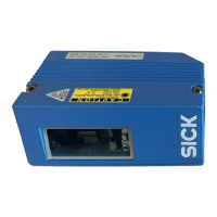
Operating Instructions
CLV 45x Bar Code Scanner
E-10
©
SICK AG · Division Auto Ident · Germany · All rights reserved 8 009 139/K949/06-06-2002
Figures and tables
Table 8-7: Troubleshooting: Oscillating mirror errors in Reading mode...........................8-13
Table 8-8: Troubleshooting: Configuration errors (parameterization) ..............................8-14
Table 9-1: Technical specifications line scanner ........................................................................ 9-1
Table 9-2: Technical specifications line scanner with oscillating mirror............................. 9-2
Table 10-1: Reading conditions for specification diagrams ....................................................10-2
Table 10-2: Overview CLV 45x specification diagrams ............................................................10-2
Table 10-3: CLV 450: Optimum of scanning frequencies ....................................................10-17
Table 10-4: CLV system messages ..............................................................................................10-19
Table 10-5: Default settings of CLV-Setup (extract)...............................................................10-22
Table 10-6: Function of the preprinted Profile bar codes on card No. 8 008 085....10-33
Table 10-7: Auxiliary table for calculating the code length of a bar code.......................10-39
Table 10-8: Communication parameters to be set on the terminal/PC for the
auxiliary input .................................................................................................................10-47
Table 10-9: Communication parameter to be set for the ST 1100 decoder...............10-48
Table 10-10: Available accessories: Mounting accessories ..................................................10-51
Table 10-11: Available accessories: Connection modules.....................................................10-51
Table 10-12: Accessories: Bus Connection modules...............................................................10-52
Table 10-13: Available accessories: Cables and connectors................................................10-52
Table 10-14: Available accessories: Network controller..........................................................10-53
Table 10-15: Supplementary documentation in English ..........................................................10-56
Figures
Fig. 2-1: Laser warning label attached to the CLV (valid for Europe)................................. 2-2
Fig. 3-1: Design of the line scanner CLV 45x.............................................................................. 3-3
Fig. 3-2: Design of the line scanner with oscillating mirror CLV 45x .................................. 3-4
Fig. 3-3: Block diagram: Functions of the CLV ............................................................................ 3-5
Fig. 3-4: Focal position changeover: Division of the overall reading range into
distance configurations ...................................................................................................... 3-6
Fig. 3-5: Oscillating mirror: Example of the focal position changeover in the
search run ............................................................................................................................... 3-7
Fig. 3-6: LEDs .......................................................................................................................................... 3-8
Fig. 4-1: Example of line scanner: Exchanging the laser warning label............................. 4-2
Fig. 4-2: Example of line scanner: Position of the fastening thread at the CLV............. 4-3
Fig. 4-3: Line scanner: Example of the mounting possibilities of the CLV with the
mounting bracket No. 2 020 410 ................................................................................. 4-3
Fig. 4-4: Line scanner: Example of the mounting possibilities of the CLV with the
mounting bracket No. 2 022 564 ................................................................................. 4-4
Fig. 4-5: Positioning of the scanning process to the bar code and to the conveyor
direction ................................................................................................................................... 4-4
Fig. 4-6: Definition of the reading distance a and of the aperture angle a...................... 4-5
Fig. 4-7: Line scanner: Reading angle occurring between the scan line and
the bar code........................................................................................................................... 4-5
Fig. 4-8: Avoiding surface reflections: Angle between the emitted light and
the bar code (tilted away from the perpendicular).................................................. 4-6
Fig. 4-9: Counting direction of the code position CP within the scan line and
of the code angle CW at an oscillating mirror............................................................ 4-7
Fig. 4-10: Line scanner: Appearance of the scan line in the "Adjusting mode"
operating mode...................................................................................................................4-10
Fig. 4-11: Correction of the printed terminal assignment in the connection area
of the AMV/S 40.................................................................................................................4-11
Fig. 4-12: Line scanner: Installation example for positioning the external
reading-pulse sensor ........................................................................................................4-12
Fig. 4-13: CLV 44x: Installation example for positioning the object distance
detection................................................................................................................................4-13
Fig. 5-1: Block diagram: Connection of the CLV to the AMV/S 40 connection
module...................................................................................................................................... 5-1

 Loading...