Chapter 6 Operating Instructions
CLV 45x Bar Code Scanner
6-8
©
SICK AG · Division Auto Ident · Germany · All rights reserved 8 009 139/K949/06-06-2002
Operation
6.4.3 Guide to parameterization
Overview of parameterization steps
•
Adjusting the optical read properties of the scanner
•
Configuring a reading trigger
•
Adjusting the decoder’s evaluation properties
•
Adjusting the output properties (data, result status)
•
Specifying the terminal interface function (auxiliary data interface)
When the CLV is switched on for the first time, it is started with the factory default setting.
The following parameters must then be set:
a) Adjusting the optical reading properties
•
Scanning frequency
Ö
R
EADING
CONFIGURATION
tab card
Ö
Reading parameters
•
Blank zone
Ö
R
EADING
CONFIGURATION
tab card
Ö
Segmentation
•
Poor quality bar code print
Ö
R
EADING
CONFIGURATION
tab card
Ö
Code label quality
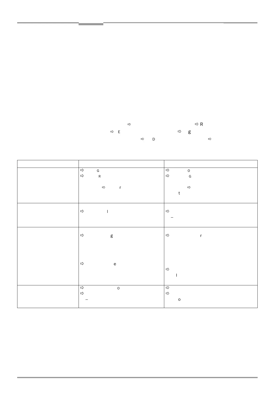
Setting up the focal position changeover
Table 6-4: Guide: Parameterizing the changeover of the distance configuration/focal position
Note The limitation of the active evaluation range of the scan line (M
IN
.
AND
MAX
.
CODE
POSITION
)
can be checked in the S
HOW
CP
LIMITS
mode (refer to
Chapter 6.5.4 Show CP limits,
Page 6-23
).
Action Line scanner Line scanner with oscillating mirror
1. Activate changeover of dis-
tance configuration/focal po-
sition
(select trigger source)
Ö
R
EADING
CONFIGURATION
tab card
Ö
F
OCUS
TRIGGER
SOURCE
– Inputs/Serial or
–Timer
Ö
T
IMER
or
– Static/no triggering
Ö
R
EADING
CONFIGURATION
tab card
Ö
F
OCUS
TRIGGER
SOURCE
– Inputs/Serial or
–Timer
Ö
T
IMER
or
– Static/no triggering or
–
Oscillating mirror extrema
2. Select the changeover point
(referenced to reading pulse)
F
OCUS
TRIGGER
SOURCE
Ö
Inputs/Serial
– Immediate or synchronous
–Latched
F
OCUS
TRIGGER
SOURCE
Ö
Inputs/Serial
– Immediate or synchronous
–Latched
3. Set up distance configura-
tions/focal positions
D
ISTANCE
CONFIGURATION
/A
SSIGNMENT
TABLE
Ö
Distance configuration
– Minimum distance
– Focus position
– Minimum code position CP
– Maximum code position CP
Ö
Assignment table
–Index
– Number of valid configurations
D
ISTANCE
CONFIGURATION
/A
SSIGNMENT
TABLE
Ö
Distance configuration
– Minimum distance
– Focus position
– Minimum code position CP
– Maximum code position CP
–
Oscillating mirror amplitude CW
Ö
Assignment table
–Index
– Number of valid configurations
4. At triggering mode I
NPUTS
/
S
ERIAL
:
Select function for "Sensor 2"
switching input
Ö
D
EVICE
CONFIGURATION
tab card
Ö
A
SSIGNMENT
SENSOR
2
– Focus control
Ö
D
EVICE
CONFIGURATION
tab card
Ö
A
SSIGNMENT
SENSOR
2
– Focus control

 Loading...


