Chapter 5 Operating Instructions
CLV 45x Bar Code Scanner
5-8
©
SICK AG · Division Auto Ident · Germany · All rights reserved 8 009 139/K949/06-06-2002
Electrical installation
Hint
The switching performance of the "Sensor 1" inputs can be changed via the D
EVICE
CONFIGU
-
RATION
tab card of the CLV-Setup user interface (polarity, debouncing and behavior for the
first cycle after switching on).
¾
Click on the E
DIT
READING
TRIGGER
command button. Edit the dialog box.
The wiring of the switching input via the AMV/S 40 connection module is described in the
operating instructions "AMV/S 40 connection module "
(Order No. 8 008 292,
English edition).
Note No external pulsing is required for the "Percentage evaluation" operating mode.
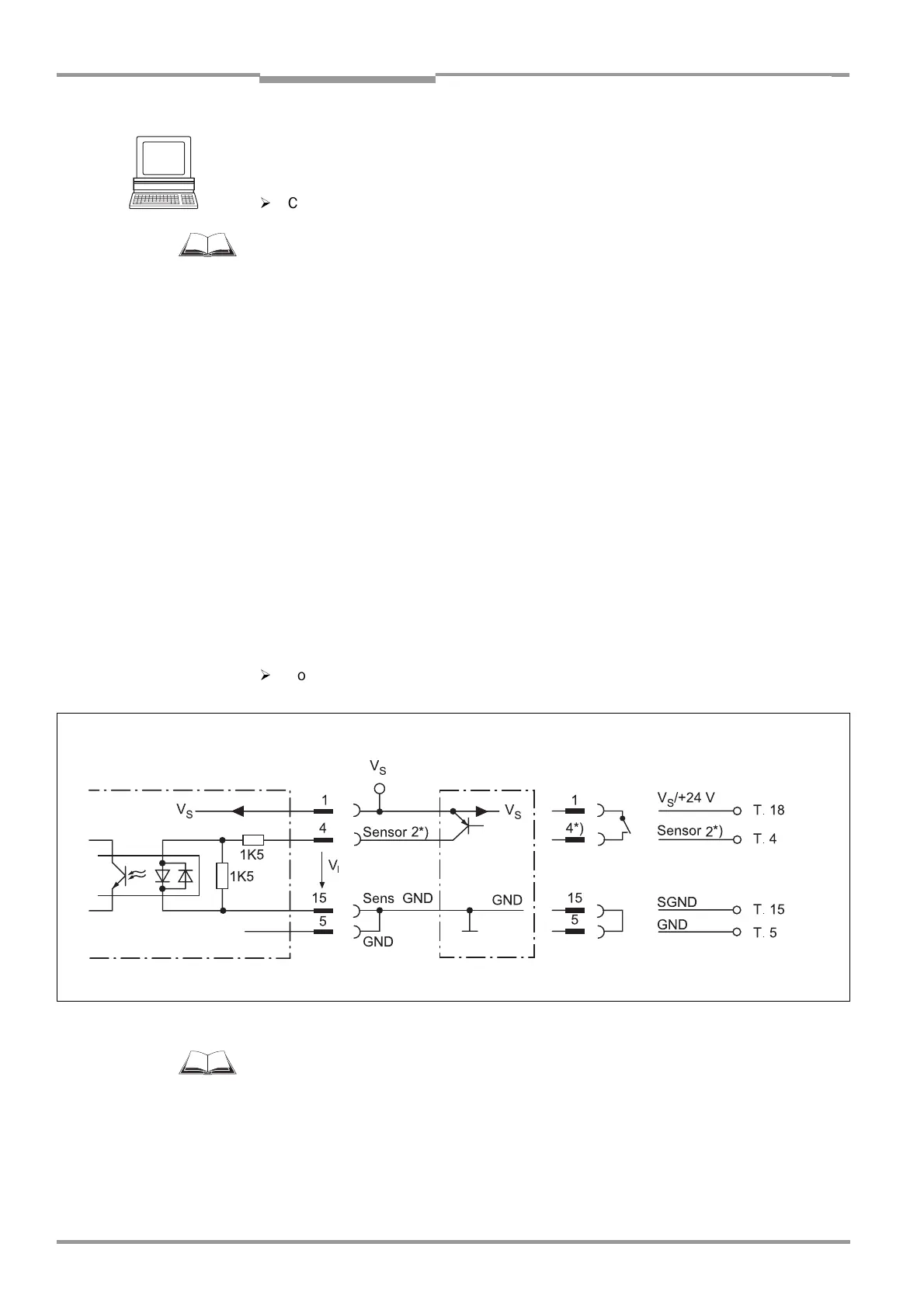
5.5.8 Wiring the "Sensor 2" switching input
If the focal position changeover is to be triggered by an external sensor, the sensor is con-
nected to the "Sensor 2" input. In combination with the internal assignment table (combina-
torics) this implements the change between two distance configurations from a max. of 8
configurations.
The input optionally has the following function for all the CLVs:
•
Trigger source for learning the match code 1 (teach-in)
•
Conveyor increment input
•
Trigger source of the One-Shot function of the oscillating mirror
In the default setting the "focal position changeover" function is selected.
The characteristic data are identical to those of the "Sensor 1" input (
Table 5-7
).
Fig. 5-5
shows the wiring of the switching input.
Table 5-8
shows the combinatorics of the
input in relation to the distance configurations.
¾
Connect the sensors as shown in
Fig. 5-5
.
The wiring of the switching input via the AMV/S 40 connection module is described in the
operating instructions "AMV/S 40 connection module"
(Order No. 8 008 292, English
edition).
Fig. 5-5: Wiring of the "Sensor 2" switching input
PNP sensor Switch
Terminal assignment
AMV 40-011/AMS 40-012, -013:
V
S
= +10 ... +30 V DC *) V
Imax
= 28 V!
CLV 45x

 Loading...


