Operating Instructions Chapter 10
CLV 45x Bar Code Scanner
Appendix
8 009 139/K949/06-06-2002
©
SICK AG · Division Auto Ident · Germany · All rights reserved
10-37
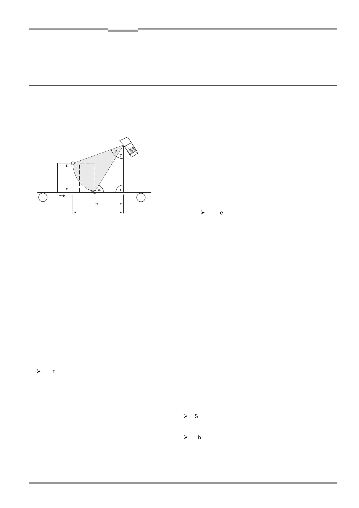
10.7.2 Calculating the start position and mirror speed for the forward and return
phase of the One-Shot function
Line scanner with oscillating mirror
Fig. 10-24: One-Shot: Line scanner with oscillating mirror: Calculating the number of scans for fence-type bar code positioning
1. Focal position for distance configuration
Theoretical calculation: Reading from the front (object moving towards CLV) Calculation for
Standard decoder!
Legend:
h
0
= Max. object height
h
S
= Distance of the CLV across conveyor level
ϕ =
Oscillating angle
α =
Max. angle of impact on bar code (skew)
Start Phase 1: Point A
Start Phase 2: Point B
γ =
90
°
–
α
ϕγ
+
()
h
s
h
0
–()
d
-------------------------=cos
ϕ
arc cos
h
s
h
0
–
()
d
---------------------------
γ–
=
StartPos 1 50 CW
ϕ
2
----
1 CW
0.5
---------------
×
+=
sin α
h
s
d
-----=
⇒
d
h
s
α
sin
-------------=
StartPos 2 50 CW
ϕ
2
----
1 CW
0.5
---------------
×
–
=
A
B
d
x
2
d
x
1
h
o
h
s
v
2. Oscillating angle
ϕ
When entering the values take the following into consideration:
– Debouncing time of the "Sensor 2" switching input
(One-Shot trigger)
– Start time of the oscillating mirror
(movement of the mass)
¾
Select the mirror speed of the return phase, depending on
the distances between the objects, so that the scan line
can be positioned on time in the starting position (Point A).
¾
Check the theoretically calculated values on site and
adapt them, if required.
3. Mirror speed
ϕ
*)
v
∆
x
∆
t
-------
∆
xx
1
x
2
–
=;=
ϕ
*
∆ϕ
∆
t
--------=
∆x
v
-------
∆ϕ
ϕ
*
-------=⇒
ϕ
*
∆ϕ
v
∆x
-------
×
with
1 °/s = 2 CW/s=
¾
Enter
ϕ
symmetrically to CW = 50 :
(Scanning direction in the drawing level)
Specified values:
h
S
> h
0
α ≤
45
°
(better:
α ≤
30
°
)
Set max. deflection angle:
±
20
°
¾
Determine distances through measurement:
x
1
= Distance at Start Phase 1
x
2
= Distance at Start Phase 2
During the period
∆
t, in which the object moves from x
1
to x
2
the oscillating mirror must also pass through the angle
∆ ϕ

 Loading...


