Chapter 5 Operating Instructions
CLV 45x Bar Code Scanner
5-4
©
SICK AG · Division Auto Ident · Germany · All rights reserved 8 009 139/K949/06-06-2002
Electrical installation
5.5 Carrying out the electrical installation
5.5.1 Overview of the connection steps
•
Connecting the supply voltage
•
Wiring the host interface
•
Connecting the PC (wiring the terminal interface)
•
Wiring the "Sensor 1" and "Sensor 2" switching inputs
•
Wiring the "Result 1" and "Result 2" switching outputs
5.5.2 Aids
•
Tool
•
Digital measuring device (current/voltage measurement)
5.5.3 Connecting the supply voltage
If the CLV is supplied with power via the AMV/S 40 connection module, the supply voltage
does not have to be wired separately.
1. Ensure that the supply voltage of the AMV/S 40 is switched off.
2. Connect the 15-pin cable plug of the CLV to the corresponding socket of the AMV/S 40
and screw it tight. The connection cable can be extended by 2 m by using the extension
cable No. 6 010 075.
The data and function interfaces of the CLV are contacted to the connection module.
– or –
In case of power supply via a non-SICK supply system device:
¾
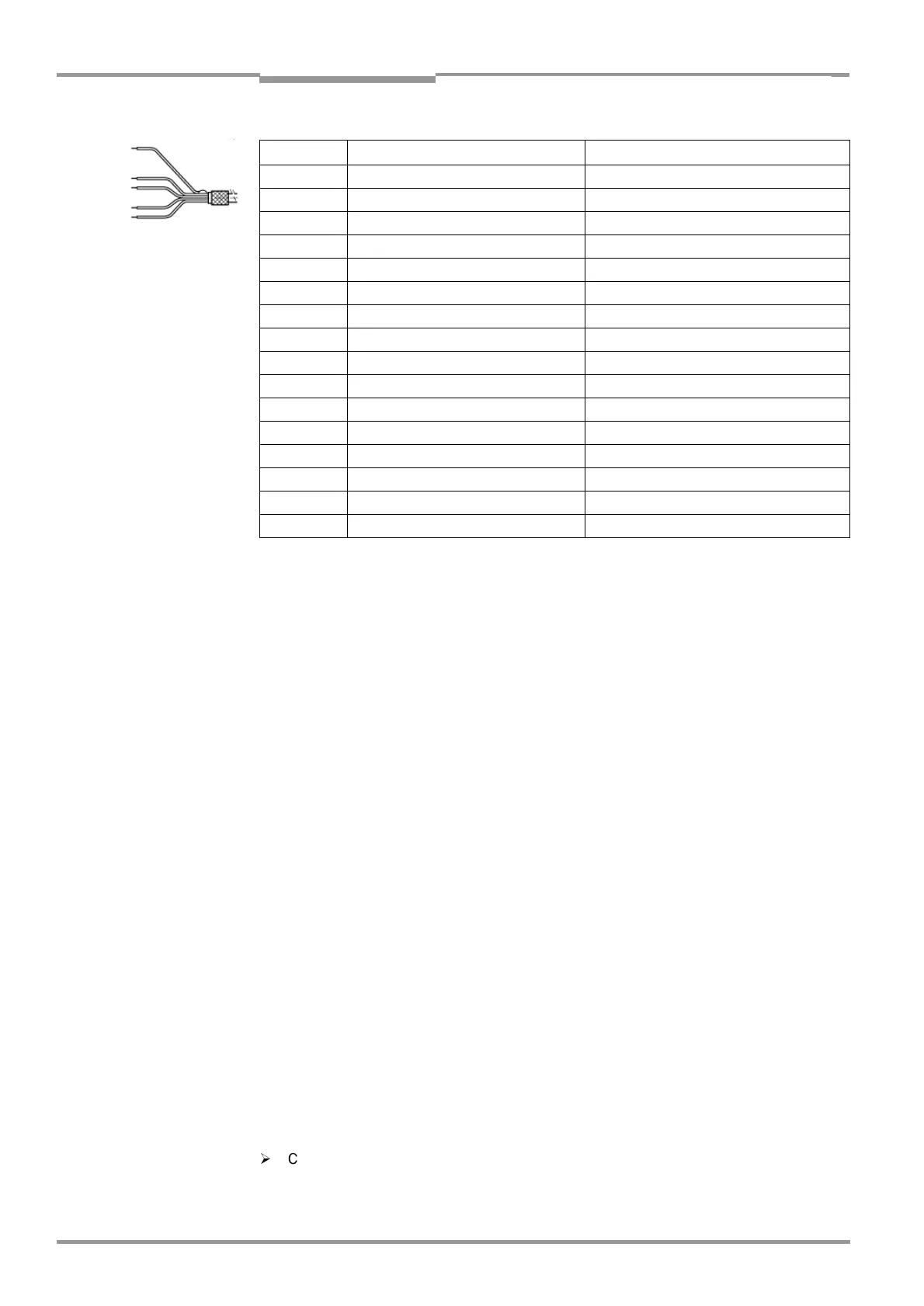
Connect the power supply to the red wire (Pin 1, +10 ... +30 V DC) and the black wire
(Pin 5, GND) of the Cable No. 6 010 137 (also refer to
Table 5-5
).
Pin Signal Wire color
1 +10 ... +30 V DC Red
2 RxD (terminal) Violet
3 TxD (terminal) Yellow
4 Sensor 2 Red-black
5 GND Black
6 RD+ (RS-422/485) Light blue
7 RD– (RS-422/485); RxD (RS-232) Blue
8 TD+ (RS-422/485) Turquoise
9 TD– (RS-422/485); TxD (RS-232) Green
10 CAN H Gray
11 CAN L Pink
12 Result 1 Brown
13 Result 2 Orange
14 Sensor 1 White
15 SensGND White-black
– Shield White-green
Table 5-5: Wire color assignment of cable No. 6 010 137 (open end)

 Loading...


