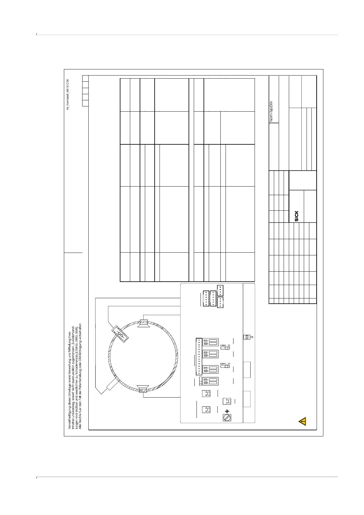
Fig. 83 Control diagram 9215965 (page 4)
SICK Engineering GmbH
Bergener Ring 27
01458 Ottendorf-Okrilla
Verteildatum:
Page
Ersatz für:
Änderung
gez.
Tag
Name
Ind.
Tag Name
Maßstab:
Werkstoff
Ersetzt durch:
Gepr.
Ursprung:
MKO
4of7
2014-07-16
Class I, Division 1, Groups C and D, Temp. Code T4
Ex ia IIB T4 Ga
ClassI,Zone0AExiaIIBT4Ga
.
-25°C < Tamb < 60°C
,
for extended range see Marking plate
.
In the US install in accordance with the NEC (NFPA70, Article 504)
and ANSI/ISA-RP12.06.01
In Canada install in accordance with CEC part 1
Exia Intrinsically Safe; Securite Intrinseque
9215965
kochami
draft
01
2014-08-27
gepr.
kochami
2014-08-27
Control drawing FLOWSIC500 isolated I/O
Optionally Exia
Temperature Sensor
Optionally Exia
pressure sensor
Ultrasonic Transducers
Temperature range
and pressure range
see Marking plate
M12
ext. Power + DO1
DO0 + DOx
M12
Wire size for all terminals: 0,14..0, 5 mm (AWG 24 ... 20)
2
4mm
(AWG 12)
2
EXT. POWER
BAT1
n.c.
DO3
DO0
+-
P1
P2
T1
T2
SENSORS
DISPLAY
LOCK
OFF ON
5..12V
NAMUR
4,5..16V
1.5 mm²
(AWG 16)
:
R:100
S
2..16V
2..16V
DO2
2..16V
DO1
+-
BAT2
+-
+- +- +-
Connector. Function / signal Internal connection O perating
parameters
Safety
parameters*)
M12 , male,
B-coded
Pin 1 ext. power supply “–” (GND) “BAT1 –“ terminal nominal
input voltage
4.5…16 V
Ui = 20 V
Ii = 667 mA
Pi = 772 mW
Pin 2 ext. power supply “+” “BAT1 +” terminal
Pin 3 Digital output DO1 “–“ (G ND) “DO1 –“ terminal
passive,
non-isolated,
Low side switch
max.16 V
nom. 20 m A
Ron < 110 Ohm
Roff >1 MOhm
Ui = 20 V
Pi = 1.1 W
Uo = 8.2 V
Io = 0. 83 m A
Po = 1.7 mW
Co = 7.6 μF
Lo = 100 m H
Pin 4 Digital output DO1 “+“ “DO1 +” terminal
M12, male,
A-coded
Configuration
“Digital outputs HF + LF”
NAMUR / OC
optically isolated
Pin 1 Digital output DO0 “+“ “DO0 +” terminal nominal 8.2 V
Ion = 3. 4 m A
Ioff = 0.7 m A
Ui = 20 V
Pi = 1.1 W
Pin 2 Digital output DO0 “–“ “DO0 –“ term inal
Pin 3 Digital output DO2 or D O 3 “+“ “DOx +” terminal m ax.16 V
nom. 20 m A
switchable as
NAMUR
nominal 8.2 V
Ion = 3. 4 m A
Ioff = 0.7 m A
Pin 4 Digital output D O2 or DO 3 “–“ “DOx –“ term inal
Pre-selected Configuration for circular connectors M12, male
Configuration “ 2 Digital outp uts HF (Encoder) + LF”
*) values apply for the interconnection of all circuits within each connector
P2
T2
kochami
Ed.6
02
WARNING: EXPLOSION HAZARD
Substitution of components may impair Intrinsic safety
AVERTISSEMENT: La substituti on
de composants peut compromettre la securite intrinseque.
RISQUE D` EXPLOSION -
2015-09-24
kochami
ZY57
03
2018-05-02