140
8024638/AE00/V1-0/2019-09| SICKSERVICE MANUAL | MCS200HW
Subject to change without notice
5 REPAIRS
Fig. 228: Disconnecting the upper electronics unit cable
4 Remove the upper electronics unit.
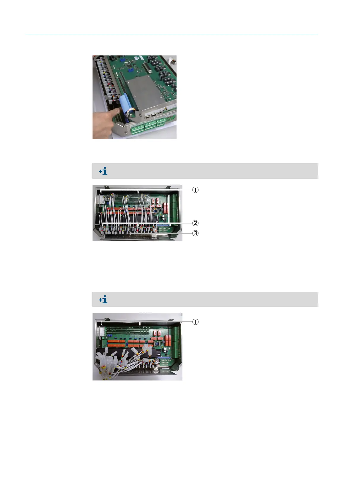
Fig. 229: LPMS02 overview 1
5 Disconnect the fuse cable from the circuit board.
Fig. 230: LPMS02 overview 2
6 Remove the cover template:
1 Loosen the fastening screws with a Phillips screwdriver (2 pieces) (see Fig. 229
“LPMS02 overview 1”, page 140).
2 Remove the cover template.
Document the plug positions of the fuse cables for reassembly. E.g. with a photo or use
the circuit diagram.
1 Cover template fastening screw
2 LPMS02 fastening screw
3Fuse cable
The fuses are fixed at one end in the housing of the lower electronics unit.
1 Cover template studs

 Loading...

