7SR11 & 7SR12 Performance Specification
©2017 Siemens Protection Devices Limited Chapter 3 Page 54 of 56
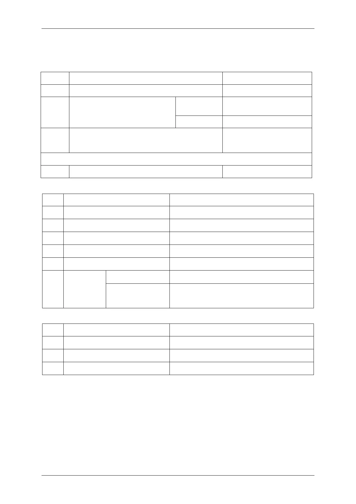
3.3 60CTS & 60CTS-I Current Transformer Supervision
3.3.1 Reference
Parameter Value
I
thresh
Current Threshold
0.05, 0.1… 2 xIn
I
Applied Current
(for operate time)
Healthy CT
Phases
5 x I
thresh
Failed CT phase 0
t
d
Delay setting
0.3, 20.00, 20.50… 100, 101…
1000, 1010… 10000, 10100…
14400 s
Directional Relays have additional VT settings
V
thresh
Voltage Threshold 7, 8… 110V
3.3.2 Current & Voltage Threshold
Attribute Value
I
op
CT failed current level
100 % I
thresh
, ± 5% or ± 1% In
Reset level
90 % I
op,
± 5% or ± 1% In
V
op
CT failed voltage level
100 % V
thresh
, ± 2% or ± 0.5V
Reset level
110 % V
op
, ± 2 % or ± 0.5V
Repeatability
± 1 %
Variation
-10 °C to +55 °C
≤ 5 %
f
nom
± 5 %
harmonics to f
cutoff
≤ 5 %
3.3.3 Operate and Reset Time
Attribute Value
t
basic
Basic operate time
50 ms ± 20ms
Operate time
t
d
+ t
basic
, ± 1 % or ± 20ms
Repeatability
± 1 % or ± 20ms

 Loading...


