7SR11 & 7SR12 Commissioning and Maintenance Guide
©2017 Siemens Protection Devices Limited Chapter 6 Page 68 of 72
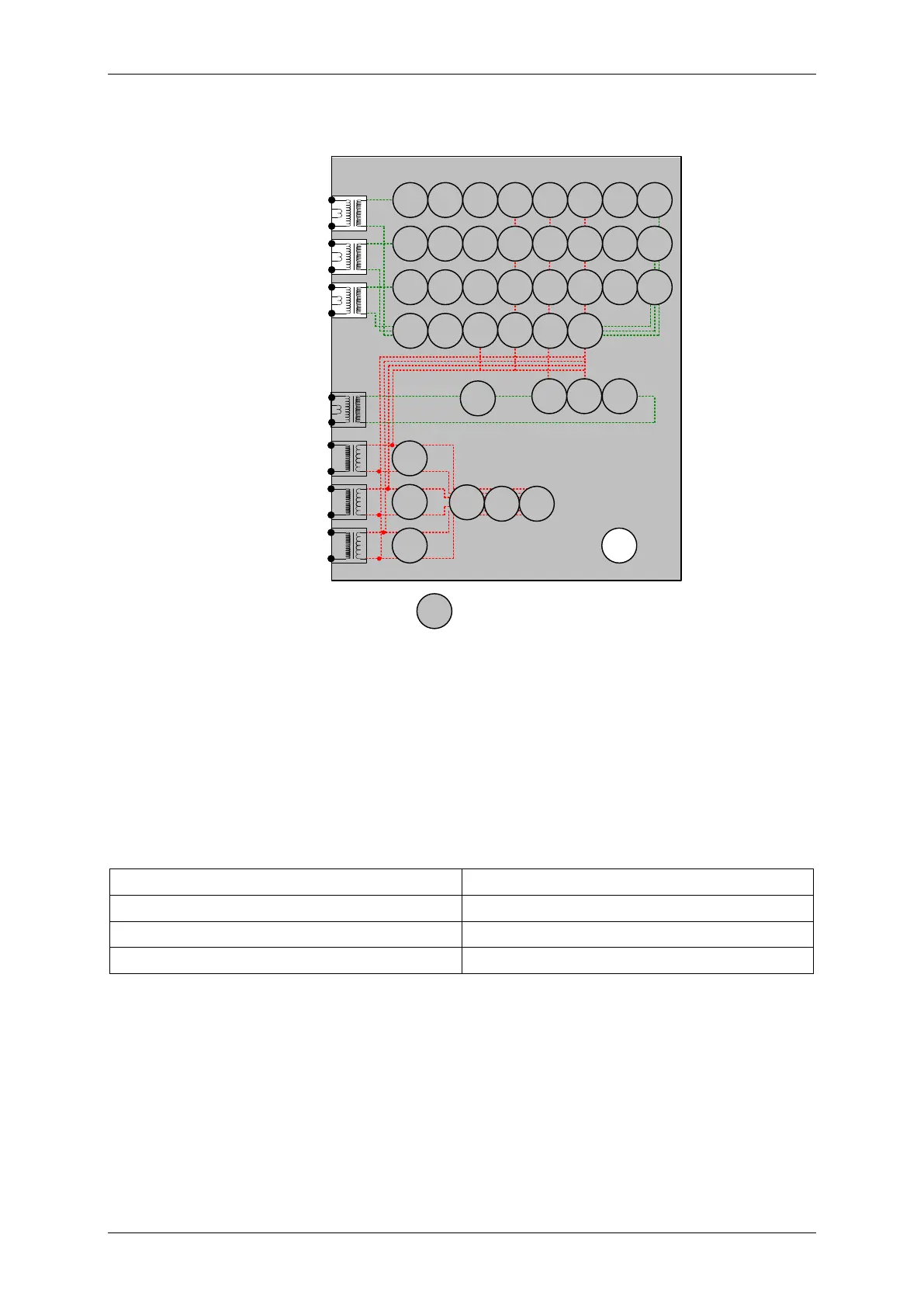
3.5 Trip/Close Circuit Supervision (74T/CCS)
7SR12
46
BC
46
NPS
(x2)
37
(x2)
49
50
BF
51V
V
L1
(V
A
)
V
L2
(V
B
)
V
L3
(V
C
)
I
L1
(I
A
)
81
HBL
2
37
(x2)
49
50
BF
51V
I
L2
(I
B
)
81
HBL
2
37
(x2)
49
50
BF
51V
I
L3
(I
C
)
81
HBL
2
I
4
(I
G
)
74
T/
CCS
NOTE: The use of some
functions are mutually exclusive
67/
50
(x4)
67/
51
(x4)
67/
50N
(x4)
67/
50
(x4)
67/
50
(x4)
67/
51
(x4)
67/
51
(x4)
67/
51N
(x4)
67/
50
SEF
67/
51
SEF
27
59
(x4)
27
59
(x4)
27
59
(x4)
79
Optional
Note:
Example shows
Voltage Config =
Van, Vbn, Vcn
60
CTS
60
VTS
50
BF
51c
51c
51c
64H
47
(x2)
59N
(x2)
81
(x4)
Figure 2-27 Trip Circuit Supervision
Voltage Inputs: n/a
Current Inputs: n/a
Disable:
Map Pickup LED: 74TCS-n - Self Reset
The T/CCS-n Delay can be initiated by applying an inversion to the relevant status input and measured by
monitoring of the alarm output.

 Loading...


