7SR11 & 7SR12 Description Of Operation
©2017 Siemens Protection Devices Limited Chapter 1 Page 51 of 88
Where: θF = final thermal state before disconnection of device
49 Overload Setting I
θ
is expressed as a multiple of the relay nominal current and is equivalent to the factor k.
IB
as defined in the IEC255-8 thermal operating characteristics. It is the value of current above which 100% of
thermal capacity will be reached after a period of time and it is therefore normally set slightly above the full load
current of the protected device.
The thermal state may be reset from the fascia or externally via a binary input.
Thermal overload protection can be inhibited from:
Inhibit 49 A binary or virtual input.
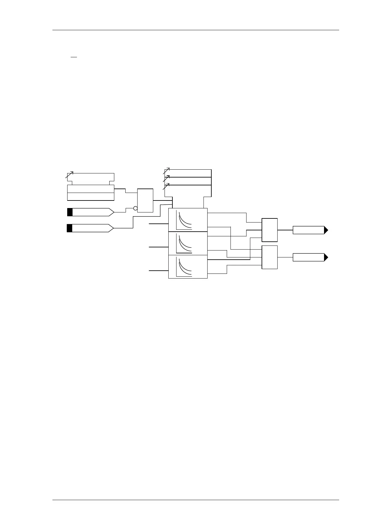
IL
1
49 Alarm
49 Trip
49 Time Constant
49 Capacity Alarm
49
Overload
Setting
c
cap alarm
trip
IL2
IL3
cap alarm
trip
cap alarm
trip
Inhibit 49
49 Therm. Overload
Enabled
Disabled
&
1
1
Reset 49
r
Figure 3-22 Logic Diagram: Thermal Overload Protection (49)
3.10 Current Protection: Line Check 50LC, 50G LC and 50SEF
LC – Only software option ‘C’
This feature prevents a CB being repeatedly manually closed onto a faulted line. It is enabled upon the
Manual CB Close output being issued.
If a fault is detected following closure, the Relay will trip for Line Check. A fault is detected if the
measured current is above the LC-n Setting level for a period greater than the LC-n Delay.
Two line check elements are provided, LC-1 and LC-2, for each fault type - phase and earth / sensitive earth
– in the CURRENT PROT’N > LINE CHECK menu.
The feature will remain enabled until the CB has been closed for a duration equal to the Close CB
Pulse + Reclaim Timer settings in the CIRCUIT BREAKER MENU. Alternatively, the element will
remain enabled as long as the Line Check binary input is energised.

 Loading...


