7SR11 & 7SR12 Commissioning and Maintenance Guide
©2017 Siemens Protection Devices Limited Chapter 6 Page 64 of 72
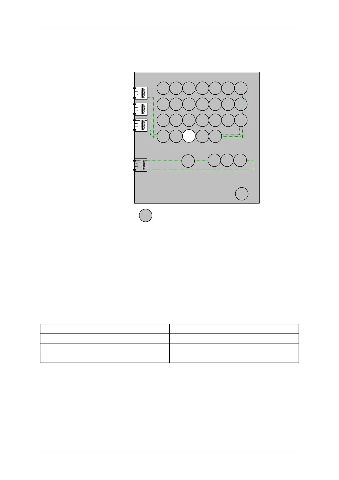
3.3 Current Transformer Supervision (60CTS)
3.3.1 7SR11
7SR11
46
BC
46
NPS
(x2)
37
(x2)
49
50
BF
I
L1
(I
A
)
81
HBL
2
37
(x2)
49
50
BF
I
L2
(I
B
)
81
HBL
2
37
(x2)
49
50
BF
I
L3
(I
C
)
81
HBL
2
I
4
(I
SEF
)
74
T/
CCS
NOTE: The use of some
functions are mutually exclusive
50
(x4)
51
(x4)
50N
(x4)
50
(x4)
50
(x4)
51
(x4)
51
(x4)
51N
(x4)
50
SEF
51
SEF
79
Optional
60
CTS
50
BF
51c
51c
51c
64H
Figure 2-24 Current Transformer Supervision 7SR11
Current Inputs: I
L1
(I
A
), I
L2
(I
B
), I
L3
(I
C
)
Disable: 51N, 46IT, 46DT, 46BC
Map Pickup LED: 60CTS - Self Reset
Apply 3Phase balanced current to the relay, reduce the current in any one or two phases to a level below 60CTS I
setting. Measure the delay to operation.
Gradually reduce the 3Phase current until the element resets.

 Loading...


