7SR11 & 7SR12 Applications Guide
©2017 Siemens Protection Devices Limited Chapter 7 Page 19 of 48
2.7 Directional Protection (67)
Each overcurrent stage can operate for faults in either forward or reverse direction. Convention dictates that
forward direction refers to power flow away from the busbar, while reverse direction refers to power flowing
towards the busbar.
The directional phase fault elements, 67/50 and 67/51, work with a Quadrature Connection to prevent loss of
polarising quantity for close-in phase faults. That is, each of the current elements is directionalised by a voltage
derived from the other two phases.
This connection introduces a 90° Phase Shift (Current leading Voltage) between reference and operate quantities
which must be allowed for in the Characteristic Angle setting. This is the expected fault angle, sometimes termed
the Maximum Torque Angle (MTA) as an analogy to older Electro-mechanical type relays
Example: Expected fault angle is -30º (Current lagging Voltage) so set Directional Angle to: +90° -30° = +60°.
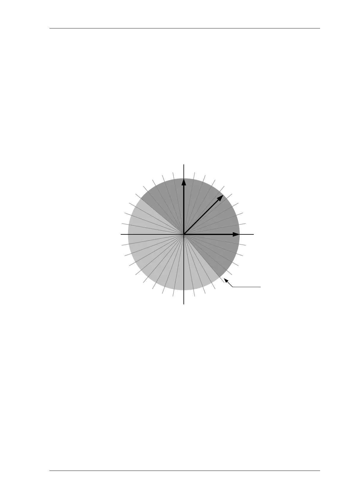
A fault is determined to be in the selected direction if its phase relationship lies within a quadrant +/- 85° either
side of the Characteristic Angle setting.
Figure 2.7-1 Directional Characteristics
A number of studies have been made to determine the optimum MTA settings e.g. W.K Sonnemann’s paper “A
Study of Directional Element Connections for Phase Relays”. Figure 2.6-1 shows the most likely fault angle for
phase faults on Overhead Line and Cable circuits.
Current
- operating
quantity
Characteristic
Angle
Volts
- polarising
quantity
OPERATING
BOUNDARY
(Zero Torque Line)
OPERATE
INHIBIT

 Loading...


