7SR11 & 7SR12 Applications Guide
Page 28 of 48 ©2017 Siemens Protection Devices Limited
2.11 Undercurrent (37)
Undercurrent elements are used in control logic schemes such as Auto-Changeover Schemes, Auto-Switching
Interlock and Loss of Load. They are used to indicate that current has ceased to flow or that a low load situation
exists. For this reason simple Definite Time Lag (DTL) elements may be used.
For example, once it has been determined that fault current has been broken – the CB is open and no current
flows – an auto-isolation sequence may safely be initiated.
2.12 Thermal Overload (49)
The element uses measured 3-phase current to estimate the real-time Thermal State, θ, of cables or
transformers. The Thermal State is based on both past and present current levels.
θ = 0% for unheated equipment, and θ = 100% for maximum thermal withstand of equipment or the Trip
threshold.
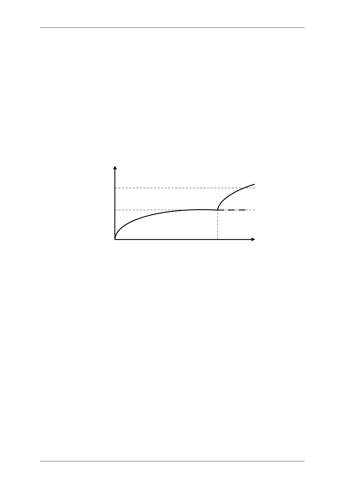
Figure 2.12-1 Thermal Overload Heating and Cooling Characteristic
For given current level, the Thermal State will ramp up over time until Thermal Equilibrium is reached when
Heating Effects of Current = Thermal Losses.
The heating / cooling curve is primarily dependant upon the Thermal Time Constant. This must be matched
against that quoted for the item of plant being protected. Similarly the current tripping threshold,
, is related to
the thermal withstand of the plant.
Thermal Overload is a slow acting protection, detecting faults or system conditions too small to pick-up fast acting
protections such as Phase Overcurrent. An Alarm is provided for θ at or above a set % of capacity to indicate that
a potential trip condition exists and that the system should be scrutinised for abnormalities.
θ
TIME
100%
0%
Thermal Equilibrium
Trip
Overload ?

 Loading...


