7SR11 & 7SR12 Applications Guide
Page 22 of 48 ©2017 Siemens Protection Devices Limited
2.8 Directional Earth-Fault (50/51G, 50/51N, 50/51SEF)
The directional earth-fault elements, either measured directly or derived from the three line currents the zero
sequence current (operate quantity) and compare this against the derived zero phase sequence voltage
(polarising quantity). Chapter 1 of the Technical Manual ‘Description of Operation’ details the method of
measurement. The required setting is entered directly as dictated by the system impedances.
Example: Expected fault angle is -45° (i.e. residual current lagging residual voltage) therefore 67G Char Angle =
-45°
Derived directional earth elements, 50N and 51N, can be selectable to use either ZPS or NPS Polarising. This is
to allow for the situation where ZPS voltage is not available; perhaps because a 3-limb VT is being used. NPS
polarising uses the phase of the NPS voltage and NPS current for directional polarising but the ZPS derived earth
fault current is still the operating quantity. Care must be taken as the Characteristic Angle may require adjustment
if NPS Polarising is used.
Once again the fault angle is completely predictable, though this is a little more complicated as the method of
earthing must be considered.
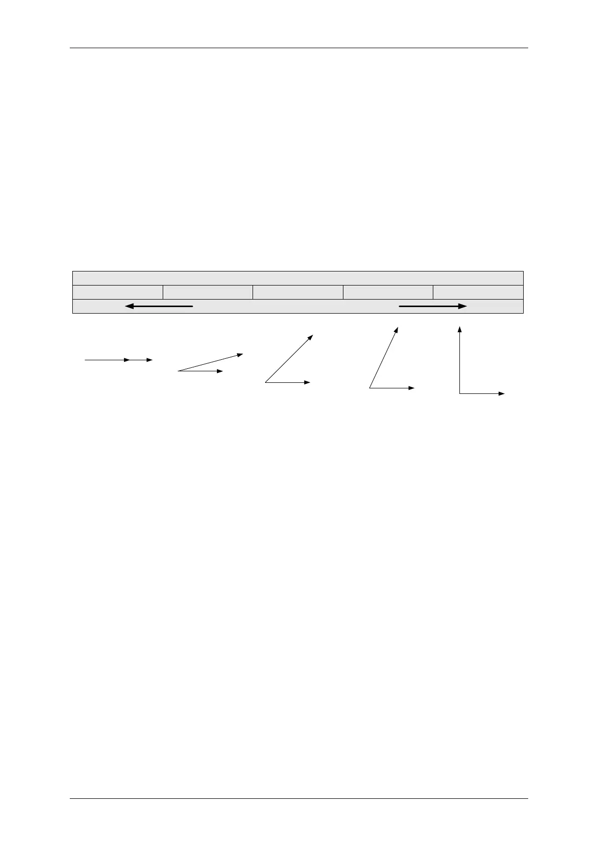
MTA (I wrt V)
O
0
-15
0
-90
0
-65
0
-45
0
Resistive Neutral Reactive Neutral
V
RES
V
RES
I
RES
I
RES
I
RES
I
RES
I
RES
V
RES
V
RES
V
RES
Resistance
Earthed
Systems
Distribution System
- Solidly Earthed
Transmission System
- Solidly Earthed
Reactance
Earthed
Systems
Earthing Transformer
with Resistor
Figure 2.8-1 Earth Fault Angles
2.8.1 Compensated Coil Earthing Networks
In compensated networks the Resonant Coil (Petersen coil) is tuned to match the capacitive charging currents
such that when an earth fault occurs, negligible fault current will flow. However, resistive losses in the primary
conductors and also in the earthing coil will lead to resistive (wattmetric) components which can be measured by
the 50/51SEF elements and used to indicate fault position. Core balance CTs are recommended for this
application to achieve the necessary accuracy of residual current measurement.

 Loading...


