7SR11 & 7SR12 Description Of Operation
©2017 Siemens Protection Devices Limited Chapter 1 Page 43 of 88
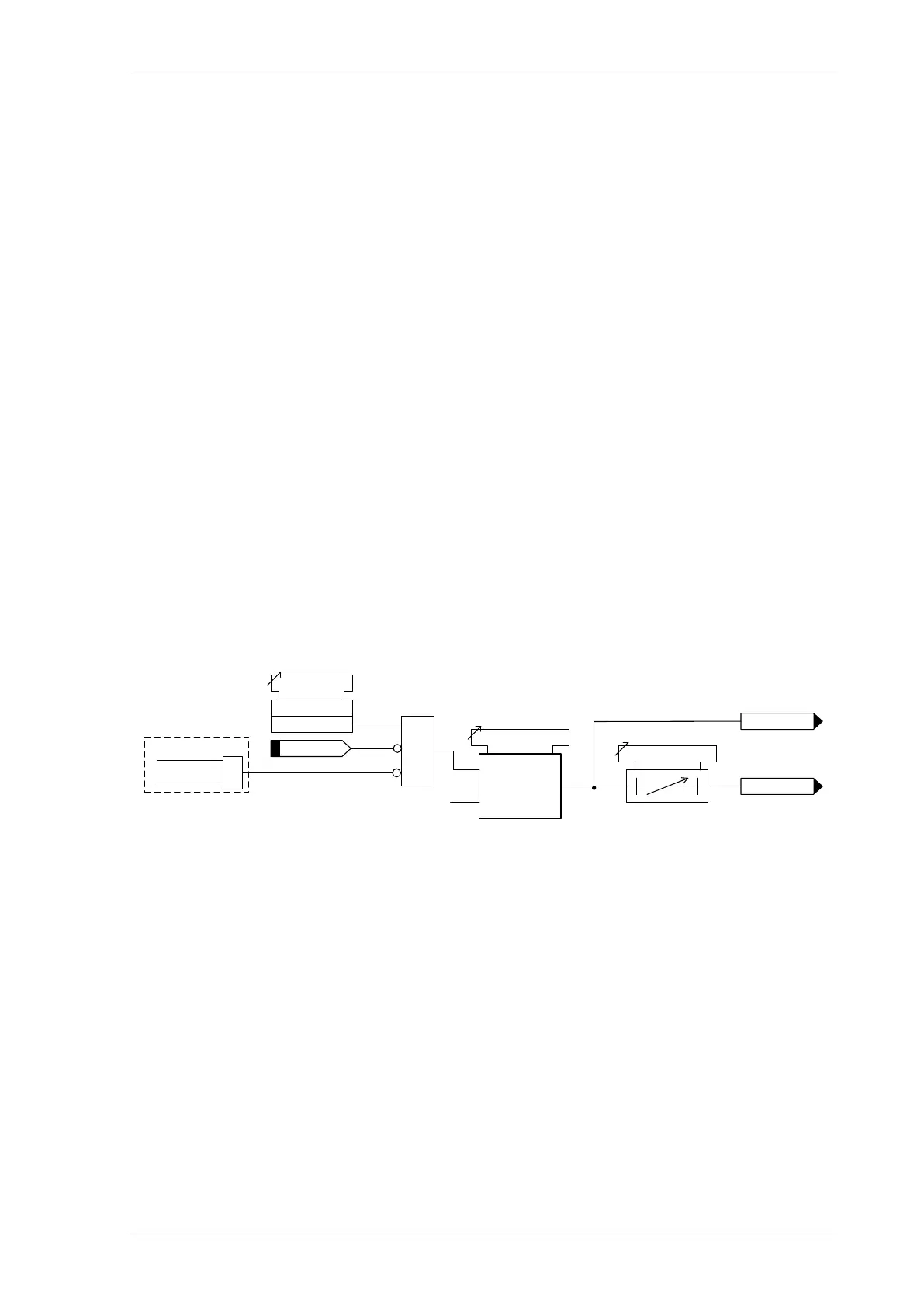
Figure 3-11 Logic Diagram: SEF Directional Element (67SEF)
3.4.2 INSTANTANEOUS SENSITIVE EARTH FAULT PROTECTION (50SEF)
Two sensitive earth fault elements are provided in the 7SR11 relay and four elements are provided in the 7SR12
relay.
50SEF-1, 50SEF-2, (50SEF-3 & 50SEF-4– 7SR12)
Each instantaneous element has independent settings for pick-up current 50SEF-n Setting and a follower time
delay 50SEF-n Delay. The instantaneous elements have transient free operation.
Where directional elements are present the direction of operation can be set using 50SEF-n Dir. Control setting.
Directional logic is provided independently for each 50SEF-n element e.g. giving the option of using two elements
set to forward and two to reverse.
Operation of the instantaneous earth fault elements can be inhibited from:
Inhibit 50SEF-n A binary or virtual input.
79 SEF Inst Trips: 50SEF-n When ‘delayed’ trips only are allowed in the auto-reclose sequence
(79 SEF Prot’n Trip n = Delayed).
50SEF-n VTSAction: Inhibit Operation of the VT Supervision function (7SR1205 & 7SR1206).
Directional elements will not operate unless the zero sequence voltage (V
0
) is above the 67SEF Minimum
Voltage setting i.e. the residual voltage is greater than 3 times this setting and the phase is in the
Forward/Reverse operating range. If 67SEF Wattmetric is set to Enabled, the calculated residual real power
must be above the 67SEF Wattmetric Power setting for any SEF element operation. The residual power P
res
is
equal to the wattmetric component of 3V
0
I
SEF
and therefore the wattmetric component of 9V
0
I
0
50SEF-n
>
c
50SEF-n Setting
50SEF-n Delay
I
4
(I
SEF
)
General Pickup
Inhibit 50SEF-n
&
50SEF-n Element
Enabled
Disabled
&
79 P/F Inst Trips
= 50SEF-n
79 P/F Prot’n Trip n
= Delayed
AUTORECLOSE
Figure 3-12 Logic Diagram: 7SR11 SEF Instantaneous Element

 Loading...


