7SR11 & 7SR12 Description Of Operation
Chapter 1 Page 20 of 88 ©2017 Siemens Protection Devices Limited
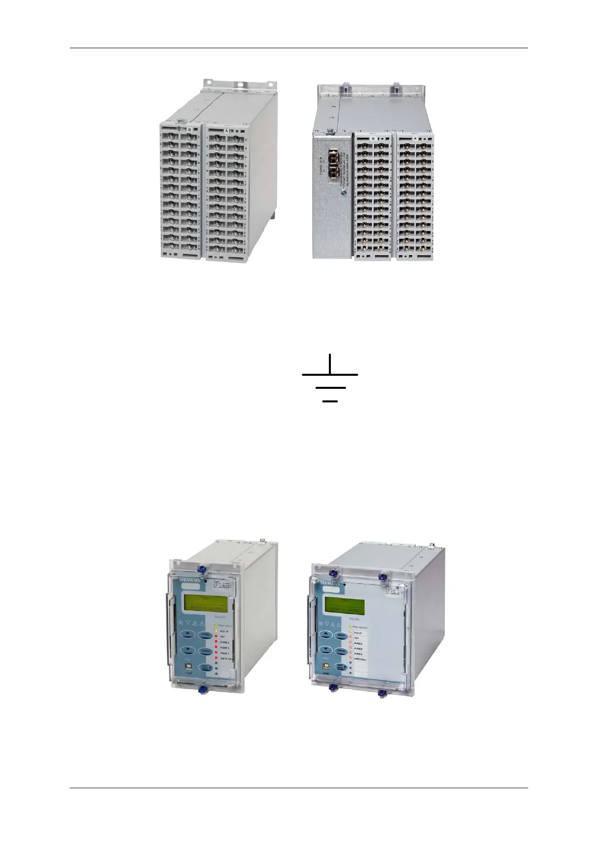
Figure 2-2 Rear view of Relay (E6 Case with optional IEC61850 module)
Located at the top rear of the case is a screw clamp earthing point, this must be connected to terminal 28 and
directly to the main panel earth. This connection point is indicated by the following symbol.
Figure 2-3 Earth connection Symbol
2.3 Front Cover
As standard the relay is supplied with a transparent front cover. The front cover is used to secure the relay
assembly in the case and it is recommended that the cover is always fitted when the relay is in service.
Figure 2-4 Relay with standard transparent cover (E6 Case with optional IEC61850 module)
If access is required to view the menus without removing the cover, an alternative transparent cover with push
buttons may be ordered. With the cover in place the user will only has access to the
▼ and TEST/RESET►
buttons, allowing all areas of the menu system to be viewed, but preventing setting changes and control actions.
The only ‘action’ that is permitted is to reset the Fault Data display, latched binary outputs and LEDs by using the

 Loading...


