7SR11 & 7SR12 Description Of Operation
©2017 Siemens Protection Devices Limited Chapter 1 Page 35 of 88
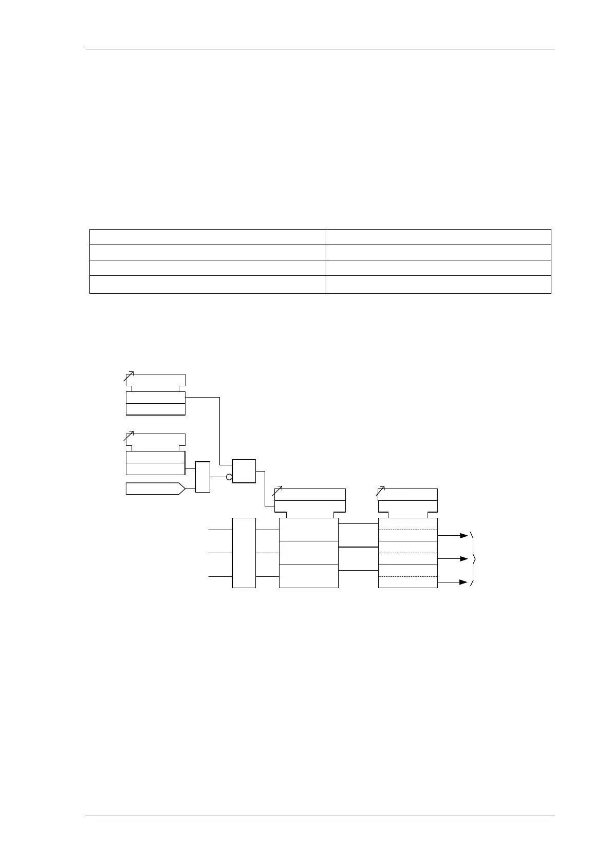
3.1.4 CURRENT PROTECTION: VOLTAGE CONTROLLED OVERCURRENT (51V) - 7SR12
Voltage controlled overcurrent is only available in relays with four current inputs.
Each shaped overcurrent element 51-n Setting can be independently controlled by the level of measured
(control) input voltage.
For applied voltages above VCO Setting the 51-n element operates in accordance with its normal current setting
(see 3.1.3). For input Ph-Ph control voltages below VCO Setting a multiplier (51-n Multiplier) is applied to
reduce the 51-n pickup current setting.
51-n Multiplier is applied to each phase independently when its control phase-phase voltage falls below VCO
Setting. The voltage levels used for each phase over-current element are shown in the table below. Relays with a
Ph-N connection automatically calculate the correct Ph-Ph control voltage.
Current Element Control Voltage
I
L1
V
12
I
L2
V
23
I
L3
V
31
The Voltage Controlled Overcurrent function (51V) can be inhibited from:
VCO VTSAction: Inhibit Operation of the VT Supervision function.
V
L1
51
V Setting
c
&
51
V Element
Enabled
Disabled
<
<
<
V
L2
V
L3
51V VTS Action
Off
Inhibit
See
Delayed
Overcurrent
(51-n)
VT Fail
&
51-n Multiplier
c
V
12
V
31
V
23
c
x IL1 51-n Setting
c
x IL2 51-n Setting
c
x IL3 51-n Setting
L3
L2
L1
Figure 3-4 Logic Diagram: Voltage Controlled Overcurrent Protection

 Loading...


