7SR11 & 7SR12 Description Of Operation
©2017 Siemens Protection Devices Limited Chapter 1 Page 49 of 88
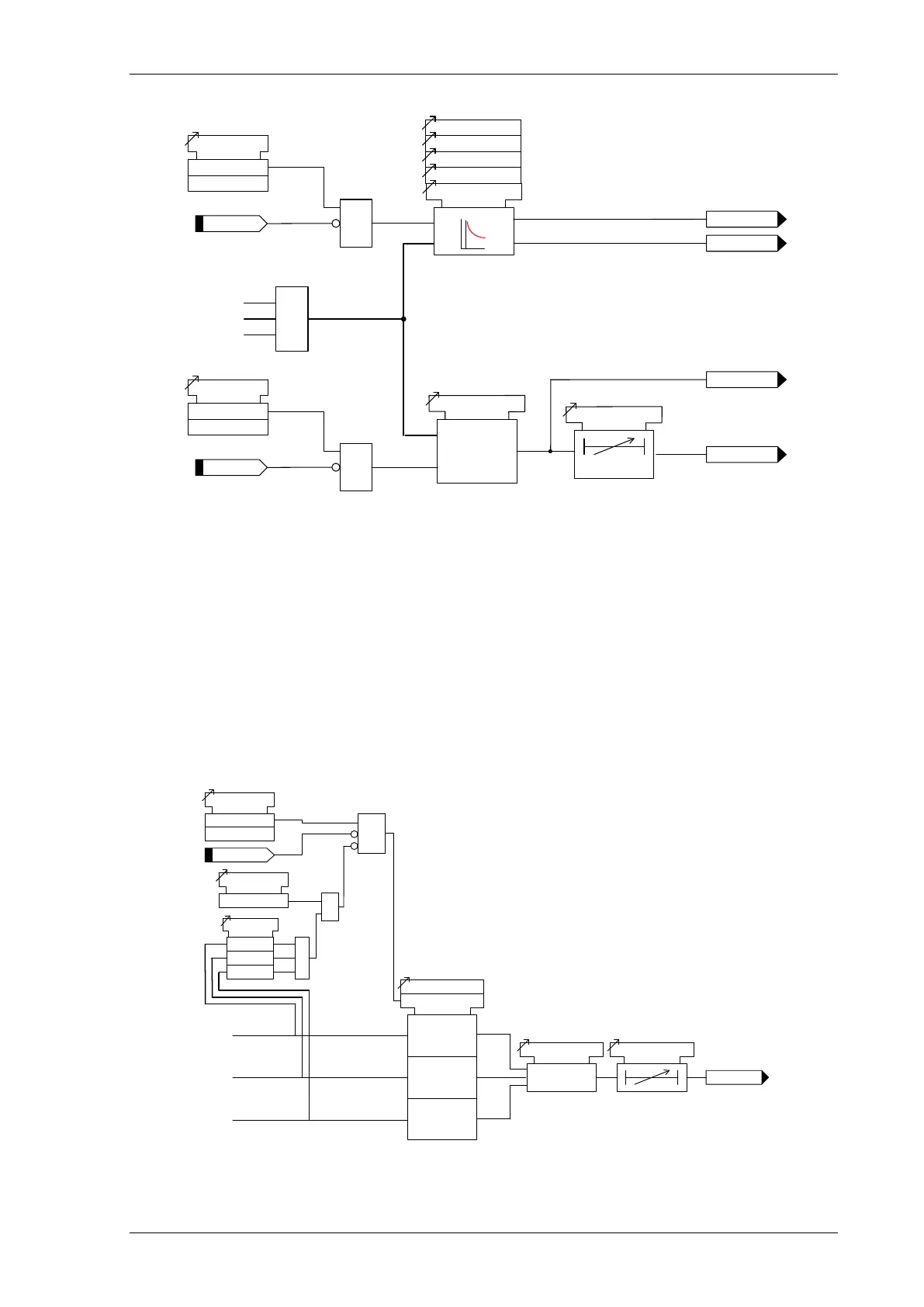
Inhibit 46IT
46
IT
46
IT Setting
46IT Char
46
IT Time Mult
46IT Delay (DTL)
46IT Element
Enabled
Disabled
&
46
IT Reset
IL
1
IL2
IL3
NPS
46DT
>
c
46
DT Setting
46DT Delay
c
Inhibit
46
DT
46DT Element
Enabled
Disabled
&
I2
General Pickup
General Pickup
c
Pickup
trip
Figure 3-18 Logic Diagram: Negative Phase Sequence Overcurrent (46NPS)
3.8 Current Protection: Under-Current (37)
Two under-current elements are provided 37-1 & 37-2 for phase currents and two for the earth or sensitive earth
fault input 37G-1 & 37G-2 or 37SEF-1 & 37SEF-2
Each phase has an independent level detector and current-timing element. 37-n Setting sets the pick-up current.
An output is given after elapse of the 37-n Delay setting.
An output is also given to indicate the operated phase.
All under-current elements work with True RMS currents.
Operation of the under-current elements can be inhibited from:
Inhibit 37-n A binary or virtual input.
37U/I Guard Setting 0.05,0.1..5xIn
IL1
37-n
37-n Delay
Inhibit
37-n
37-
n Setting
c
&
37
-n
Enabled
Disabled
<
<
<
IL2
IL3
37 U/I Guarded
Yes
&
<
&
37 U/
I Guard
Setting
<
<
37
-n Start Option
Any
/All

 Loading...


