7SR11 & 7SR12 Installation Guide
Chapter 5 Page 28 of 32 ©2017 Siemens Protection Devices Limited
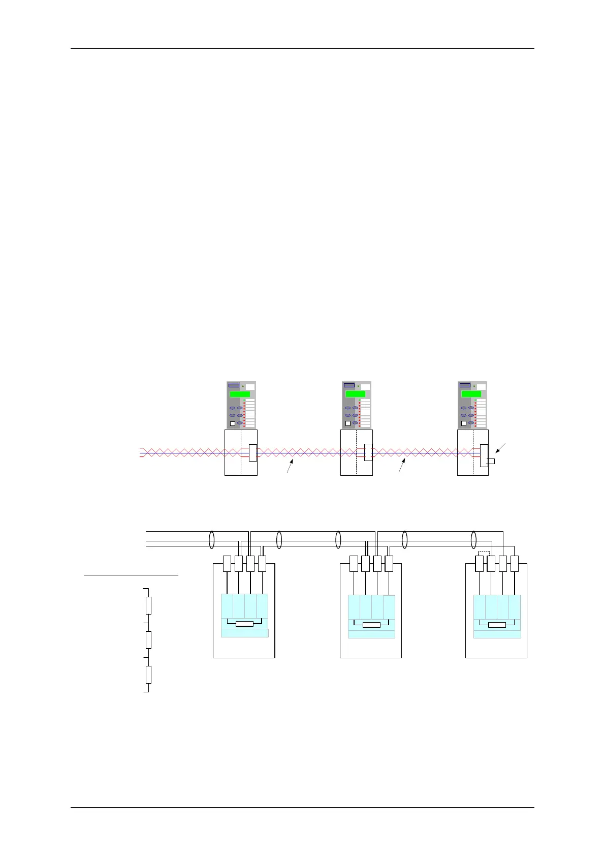
Section 6: Data Comms Connections
6.1 RS485 Connection
The RS485 communication port is located on the rear of the relay and can be connected using a suitable RS485
120Ω screened twisted pair cable.
The RS485 electrical connection can be used in a single or multi-drop configuration. The RS485 master must
support and use the Auto Device Enable (ADE) feature.
The last device in the connection must be terminated correctly in accordance with the master driving the
connection. A terminating resistor is fitted in each relay, when required this is connected in circuit using an
external wire loop between terminals 18 and 20 of the power supply module.
The polarity of the signal terminals is marked as A and B in line with the RS485 standard. The polarity is that
when the bus is in the quiescent state and no communication is taking place, the B terminal is more positive than
A. This can be used to identify the polarity of any equipment to be connected, typically measured at each terminal
in turn to ground. Connection of the device to a termination network at the end of the bus will also be to suit the
quiescent state as shown below.
The polarity marking is often found to be reversed or marked as +/- on other equipment so care is required. If the
devices are connected in reverse, communication to all devices will be disturbed but no damage will occur. If
problems are experienced during commissioning, the connections should be tried in reverse.
Up to 64 relays can be connected to the RS485 bus.
The RS485 data communications link with a particular relay will be broken if the relay element is withdrawn from
the case, all other relays will still communicate.
To Control System
14
16
18
20
RS485 Screened
twisted pair
Rear terminals
14
16
18
14
16
18
RS
485 Screened
twisted pair
Rear terminals
Ext Wire loop to
Include line
terminating Res
A
RS
485
Screen
B
Term.
14
16
18
20
14
16
18
20
14
16
18
20
RS485 Twisted pair screened cable
Bus Termination Polarity
5V
GND
B
A
To Control
System
A
RS
485
Screen
B
Term.
A
RS485
Screen
B
Term.
Figure: 6.1-1 RS485 Data Comms Connections Between Relays

 Loading...


