7SR11 & 7SR12 Description Of Operation
©2017 Siemens Protection Devices Limited Chapter 1 Page 77 of 88
&
60CTS Delay
VL1
VL2
VL3
NPS
Filter
V2
60CTS Vnps
<
IL1
IL2
IL3
NPS
Filter
I2
60CTS Inps
>
&
Inhibit 60CTS
60CTS Element
Enabled
Disabled
&
60CTS Operated
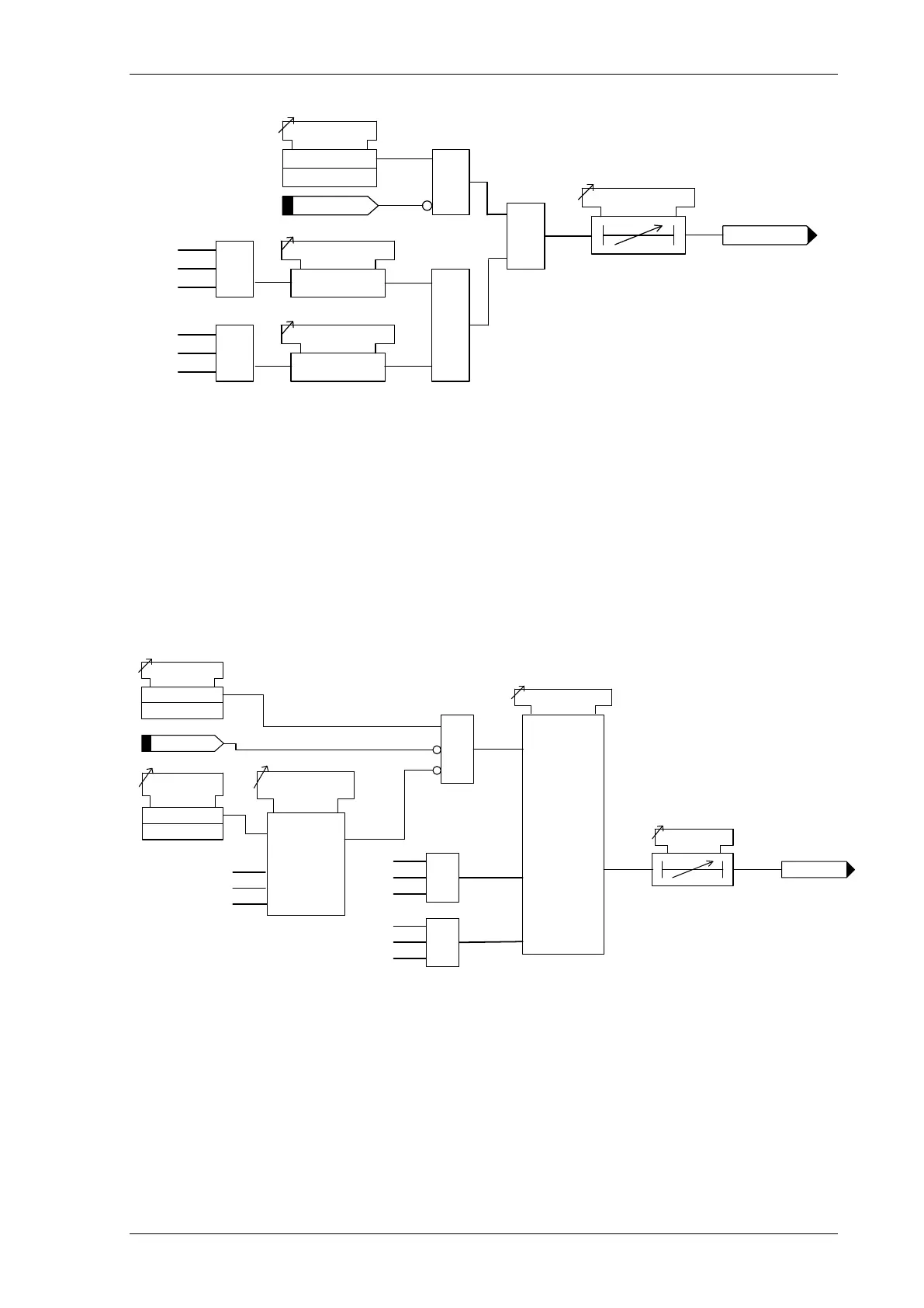
Figure 5-4 Logic Diagram: CT Supervision Function (60CTS) – 7SR12
5.4 Broken Conductor (46BC)
The element calculates the ratio of NPS to PPS currents. Where the NPS:PPS current ratio is above 46BC
Setting an output is given after the 46BC Delay.
The Broken Conductor function can be inhibited from
Inhibit 46BC A binary or virtual input.
46BC U/I Guard A minimum load current
Inhibit 46
BC
46BC
46BC Element
Enabled
Disabled
c
&
46BC Setting
IL1
IL2
IL3
NPS
Filter
I2
IL1
IL2
IL3
PPS
Filter
I1
46BC Delay
46BC U/C Guard
Setting
46BC U/C
Guarded
Yes
No
C
IL1
IL2
IL3
Figure 5-5 Logic Diagram: Broken Conductor Function (46BC)

 Loading...


