7SR11 & 7SR12 Commissioning and Maintenance Guide
©2017 Siemens Protection Devices Limited Chapter 6 Page 39 of 72
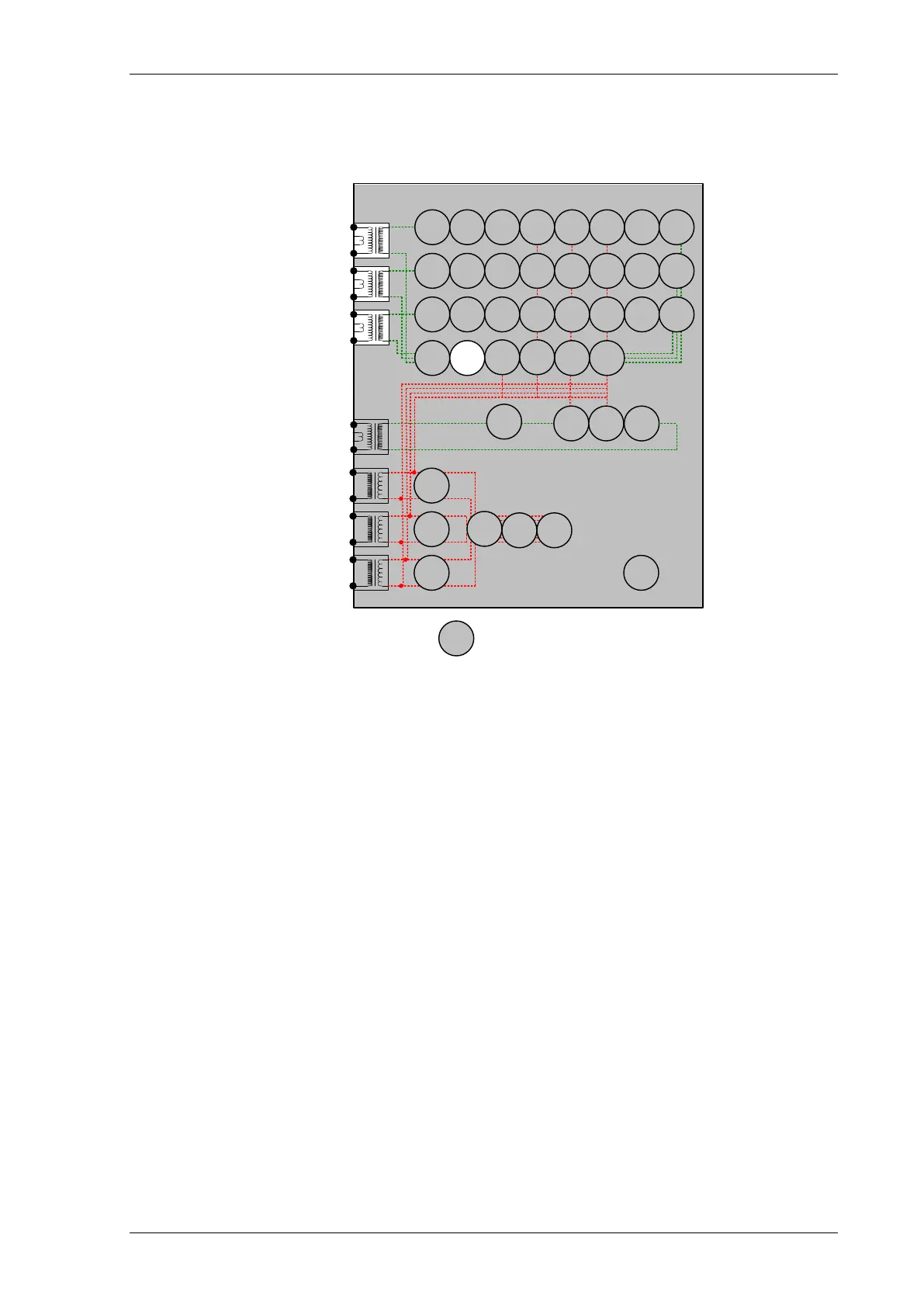
2.11 Negative Phase Sequence Overcurrent (46NPS)
7SR12
46
BC
46
NPS
(x2)
37
(x2)
49
50
BF
51V
V
L1
(V
A
)
V
L2
(V
B
)
V
L3
(V
C
)
I
L1
(I
A
)
81
HBL
2
37
(x2)
49
50
BF
51V
I
L2
(I
B
)
81
HBL
2
37
(x2)
49
50
BF
51V
I
L3
(I
C
)
81
HBL
2
I
4
(I
G
)
74
T/
CCS
NOTE: The use of some
functions are mutually exclusive
67/
50
(x4)
67/
51
(x4)
67/
50N
(x4)
67/
50
(x4)
67/
50
(x4)
67/
51
(x4)
67/
51
(x4)
67/
51N
(x4)
67/
50
SEF
67/
51
SEF
27
59
(x4)
27
59
(x4)
27
59
(x4)
47
(x2)
79
Optional
59N
(x2)
Note:
Example shows
Voltage Config =
Van, Vbn, Vcn
60
CTS
60
VTS
50BF
51c
51c
51c
64H
81
(x4)
Figure 2-12 Negative Phase Sequence Overcurrent
Voltage Inputs: n/a
Current Inputs: I
L1
(I
A
), I
L2
(I
B
), I
L3
(I
C
),
Disable: 51, 51V, 51C, 37, 49, 50CBF, 60CTS, 46BC
Map Pickup LED: 46IT/46DT - Self Reset
Where two NPS elements are being used with different settings, it is convenient to test the elements with the
highest settings first. The elements with lower settings can then be tested without disabling the lower settings.
The Thermal withstand limitations of the current inputs, stated in the Performance Specification should always be
observed throughout testing.
NPS Overcurrent can be tested using a normal 3P balanced source. Two phase current connections should be
reversed so that the applied balanced 3P current is Negative Phase Sequence.
If Phase Rotation ACB is selected in the CT/VT Config menu, the expected PPS and NPD are exchanged and
the output from a standard positive sequence test set will be considered as NPS.

 Loading...


