7SR11 & 7SR12 Description Of Operation
Chapter 1 Page 50 of 88 ©2017 Siemens Protection Devices Limited
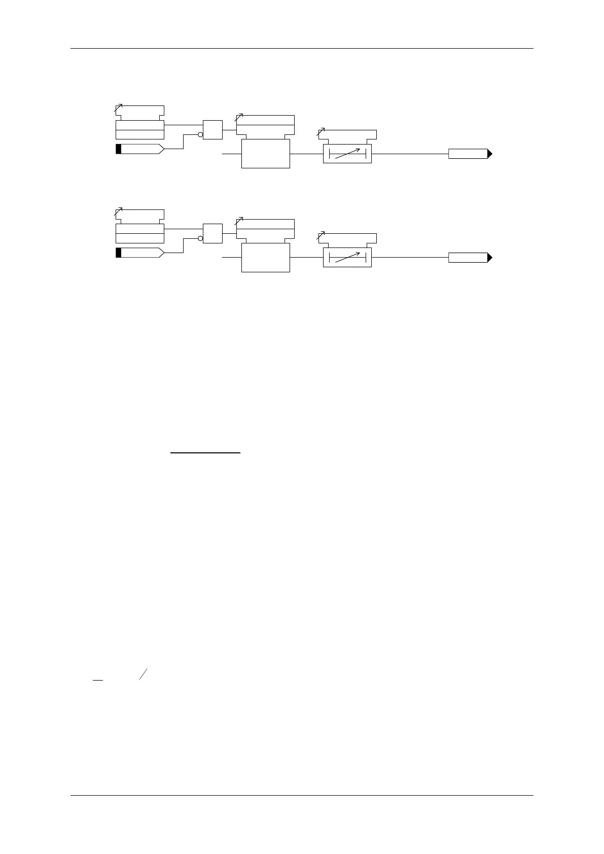
Figure 3-19 Logic Diagram: Phase Current Inputs Undercurrent Detector (37)
IL
37
G
-n
Inhibit
37
G-
n
37
G-
n Setting
c
&
37
G-
n
Enabled
Disabled
<
37
G-
n Delay
Figure 3-20 Logic Diagram: Earth Current Inputs Undercurrent Detector (37G)
IL
37SEF-n
Inhibit 37SEF-n
37SEF-n Setting
c
&
37SEF-n
Enabled
Disabled
<
37SEF-n Delay
Figure 3-21 Logic Diagram: Sensitive Earth Current Inputs Undercurrent Detector (37SEF)
3.9 Current Protection: Thermal Overload (49)
The relay provides a thermal overload suitable for the protection of static plant. Phase segregated elements are
provided. The temperature of the protected equipment is not measured directly. Instead, thermal overload
conditions are calculated using the measure True RMS current.
Should the current rise above the 49 Overload Setting for a defined time an output signal will be initiated. The
operating time is a function of thermal time constant 49 Time Constant and previous current levels.
Operate Time (t):-
( )
×
−
−
×
=
2
B
2
2
P
2
Ik
I
II
t ln
τ
Where T = Time in minutes
τ = 49 Time Constant setting (minutes)
In = Log Natural
I = measured current
IP = Previous steady state current level
k = Constant
IB = Basic current, typically the same as In
k.IB = 49 Overload Setting (Iθ)
Additionally, an alarm can be given if the thermal state of the system exceeds a specified percentage of the
protected equipment’s thermal capacity 49 Capacity Alarm setting.
For the heating curve:
Where: θ = thermal state at time t
I = measured thermal current
Iθ = 49 Overload setting (or k.IB)
The final steady state thermal condition can be predicted for any steady state value of input current where t >τ,

 Loading...


