7SR11 & 7SR12 Commissioning and Maintenance Guide
©2017 Siemens Protection Devices Limited Chapter 6 Page 25 of 72
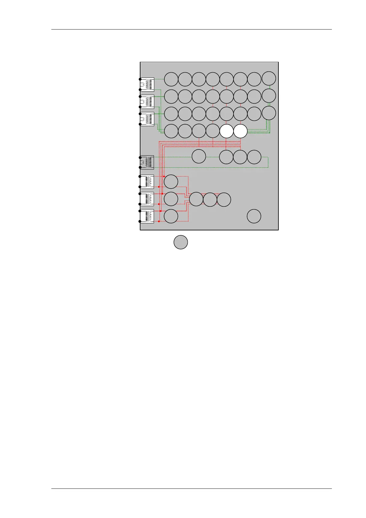
2.7 Derived Earth Fault (67/50N, 67/51N)
7SR12
46
BC
46
NPS
(x2)
37
(x2)
49
50
BF
51V
V
L1
(V
A
)
V
L2
(V
B
)
V
L3
(V
C
)
I
L1
(I
A
)
81
HBL
2
37
(x2)
49
50
BF
51V
I
L2
(I
B
)
81
HBL
2
37
(x2)
49
50
BF
51V
I
L3
(I
C
)
81
HBL
2
I
4
(I
G
)
74
T/
CCS
NOTE: The use of some
functions are mutually exclusive
67/
50
(x4)
67/
51
(x4)
67/
50N
(x4)
67/
50
(x4)
67/
50
(x4)
67/
51
(x4)
67/
51
(x4)
67/
51N
(x4)
67/
50G
(x4)
67/
51G
(x4)
27
59
(x4)
27
59
(x4)
27
59
(x4)
79
Optional
Note:
Example shows
Voltage Config =
Van, Vbn, Vcn
60
CTS
60
VTS
50BF
51c
51c
51c
64H
47
(x2)
59N
(x2)
81
(x4)
Figure 2-8 Derived Earth Fault
Voltage Inputs: V
L1
(V
A
), V
L2
(V
B
), V
L3
(V
C
)
Current Inputs: I
L1
(I
A
), I
L2
(I
B
), I
L3
(I
C
)
Disable: 37, 46, 49, 60CTS, 50CBF, 60CTS, 46BC, 79
Map Pickup LED: 51N-n/50N-n - Self Reset
Other protection functions may overlap with these functions during testing, it may be useful to disable some
functions to avoid ambiguity. Derived EF, Measured EF Sensitive EF & Restricted EF protections can be
Enabled/Disabled individually or as groups in the ‘Function Config’ menu.
Derived EF elements can be separated from Measured/Sensitive EF by arrangement of the secondary injection
circuit by shorting/disconnecting I
4
Input.
If any of these elements are defined as directional the correct voltage phase direction will be required to produce
an operation of those elements.

 Loading...


