7SR11 & 7SR12 Description Of Operation
Chapter 1 Page 18 of 88 ©2017 Siemens Protection Devices Limited
Section 2: Hardware Description
2.1 General
The structure of the relay is based upon the Reyrolle Compact hardware platform. The relays are supplied in a
size E4 or E6 case (where 1 x E = width of approx. 26mm). The hardware design provides commonality between
products and components across the Reyrolle Compact range of relays.
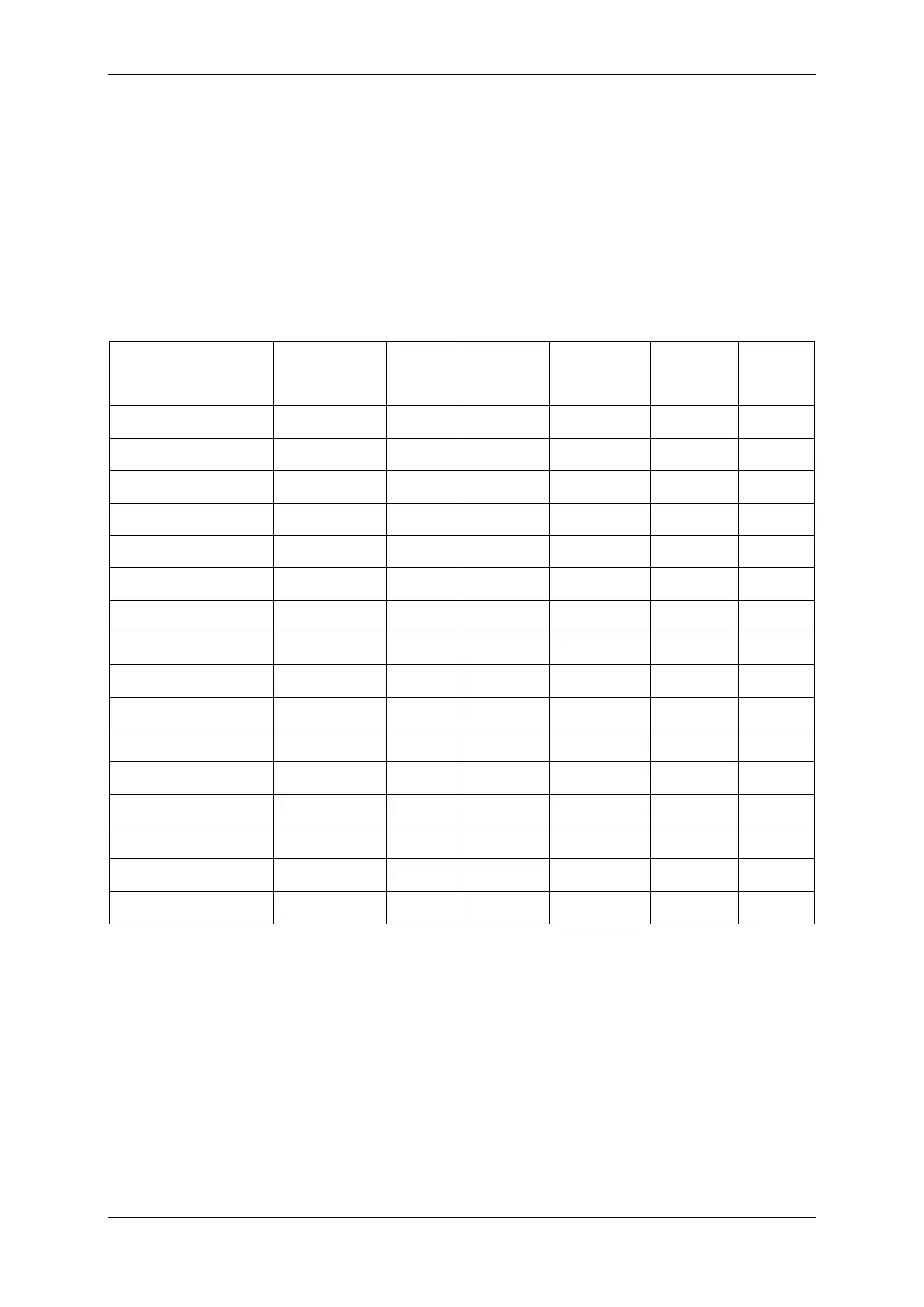
Table 2-1 Summary of 7SR1 Relay Configurations
Relay Current
Inputs
SEF
Inputs
Voltage
Inputs
Binary
Inputs
Binary
Outputs
LEDs
7SR1101-1 1 0 0 3 5 10
7SR1101-3 1 1 0 3 5 10
7SR1102-1 4 0 0 3 5 10
7SR1102-3 4 1 0 3 5 10
7SR1103-1 4 0 0 6 8 10
7SR1103-3 4 1 0 6 8 10
7SR1107-1 4 0 0 4 8 10
7SR1107-3 4 1 0 4 8 10
7SR1204-2 1 0 3 3 5 10
7SR1204-4 1 1 3 3 5 10
7SR1205-2 4 0 3 3 5 10
7SR1205-4 4 1 3 3 5 10
7SR1206-2 4 0 3 6 8 10
7SR1206-4 4 1 3 6 8 10
7SR1208-2 4 0 3 4 8 10
7SR1208-4 4 1 3 4 8 10
Relays are assembled from the following modules:
1) Front Fascia
9 configurable LEDs + 1 Relay Healthy LED
2) Processor module
3) Current Analogue / Output module
1 x Current + 5 x Binary Outputs (BO)
4 x Current + 5 x Binary Outputs (BO)
4) Voltage Analogue / Input / output module
3 x Voltage + 3 x Binary Input (BI) + 3 x Binary Output (BO)
3 x Voltage + 1 x Binary Input (BI) + 3 x Binary Output (BO) without common terminals

 Loading...


