7SR11 & 7SR12 Description Of Operation
©2017 Siemens Protection Devices Limited Chapter 1 Page 19 of 88
3 x Binary Input (BI) + 3 x Binary Output (BO)
1 x Binary Input (BI) + 3 x Binary Output (BO) without common terminals
5) Power Supply
3 x Binary Input (BI) + RS485
6) Optional Communications Module (2x Electrical Ethernet for IEC 61850) or (2x Optical Ethernet for IEC 61850).
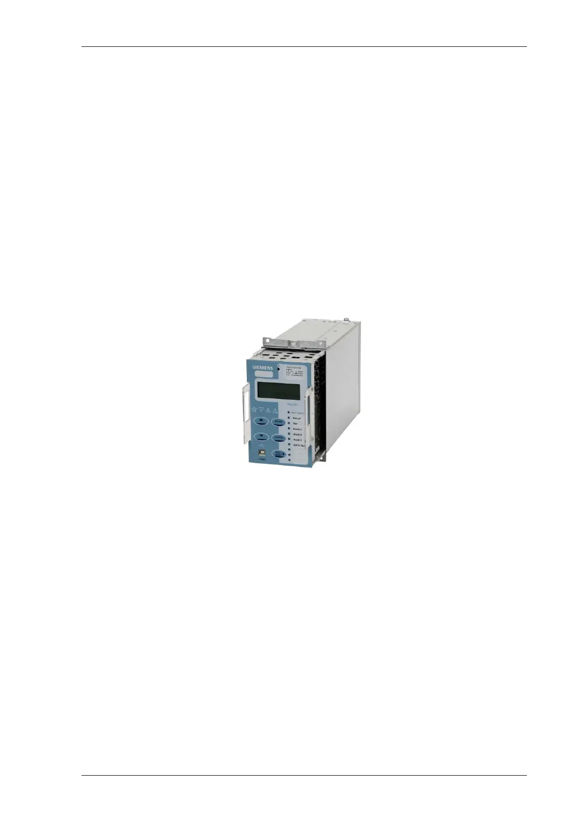
2.2 Case
The relays are housed in cases designed to fit directly into standard panel racks. The two case options have a
width of 104mm (E4) and 156 mm (E6), both have a height of 177 mm (4U). The required panel depth is
216.5mm, with wiring clearance a total of 242 mm. 290mm depth clearance should be allowed to accommodate
the bending radius of fibre optic data communications cables if fitted.
The complete relay assembly is withdrawable from the front of the case. Contacts in the case ensure that the CT
circuits and normally closed contacts remain short-circuited when the relay is removed. To withdraw the relay,
remove the plastic fascia cover by rotating the two securing pins and withdraw using the plastic handles. The
relay should not be carried using these handles. The relay should only be held by the top and bottom plates and
the user should not touch the exposed PCB’s.
Figure 2-1 E4 relay shown withdrawn
The rear terminal blocks comprise M4 female terminals for wire connections. Each terminal can accept two 4mm
crimps.

 Loading...


