7SR11 & 7SR12 Description Of Operation
©2017 Siemens Protection Devices Limited Chapter 1 Page 33 of 88
≥1
Inhibit 50-n
50-n
50-n Setting
c
50-n
Enabled
Disabled
>
c
50-n Delay
If directional elements are not
present this block is omitted and all
'Lx Dir En' signals are set TRUE.
Forward
Reverse
50-n Dir Control
Non-Dir
≥1
&
&
≥1
&
&
≥1
&
&
L1 Dir En
L2 Dir En
L3 Dir En
IL1 Fwd
IL1 Rev
IL2 Fwd
IL2 Rev
IL3 Fwd
IL3 Rev
&
&
&
≥1
≥1
≥1
50-n VTS Action
Off
Non Dir
Inhibit
VT Fail
&
&
>
c
>
c
L1 Dir En
L2 Dir En
L3 Dir En
IL1
IL2
IL3
50/51
Measurement
L1 81HBL2
50-n Inrush
Action
Off
Inhibit
&
L2 81HBL2
L3 81HBL2
&
&
&
&
&
≥1
General Pickup
&
&
79 P/F Inst Trips
= 50-n
79 P/F Prot’n Trip n
= Delayed
AUTORECLOSE
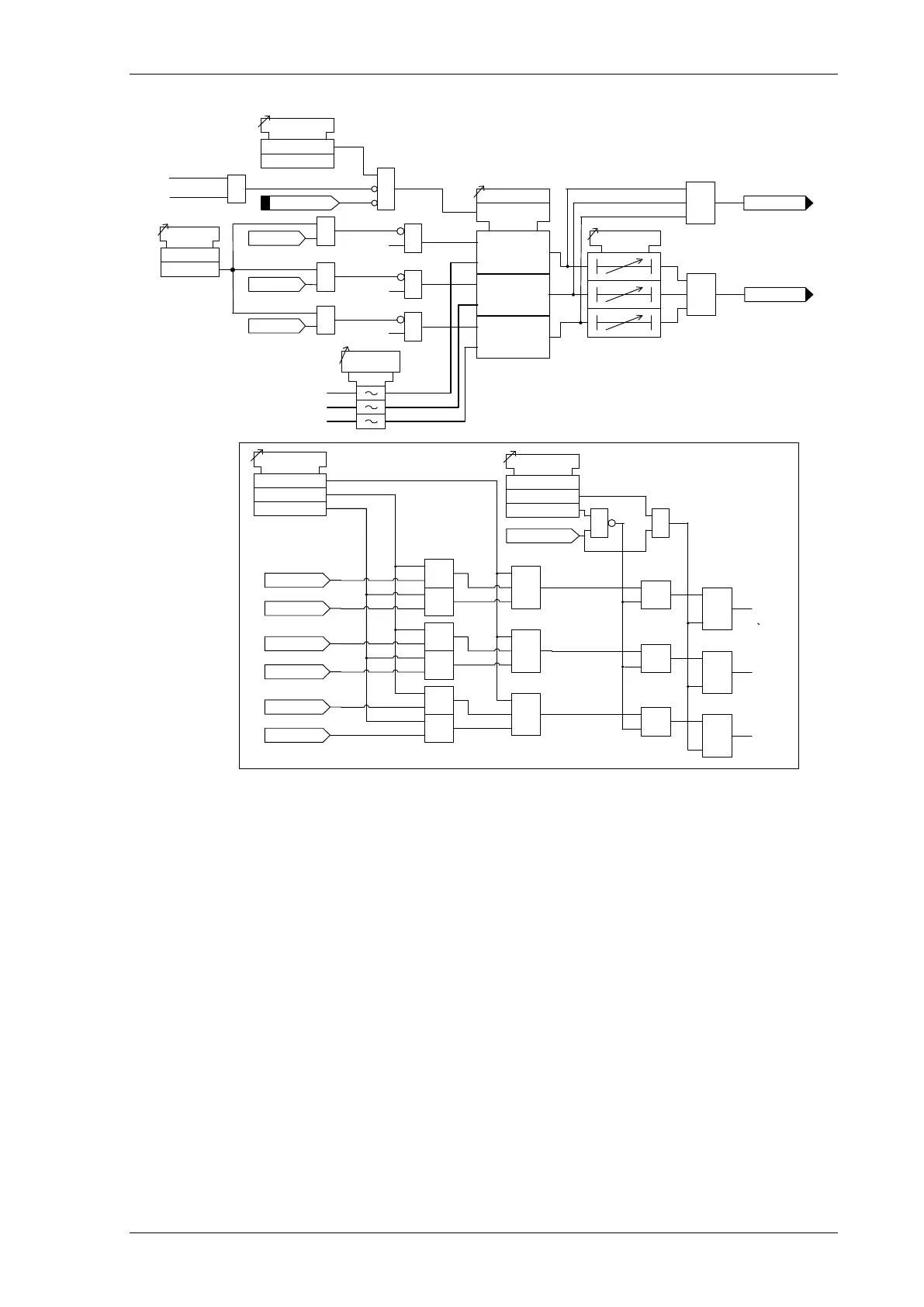
Figure 3-2 Logic Diagram: Instantaneous Over-current Element
3.1.3 TIME DELAYED OVERCURRENT PROTECTION (51)
Two time delayed overcurrent elements are provided in the 7SR11 relay and four elements are provided in the
7SR12 relay.
51-1, 51-2, (51-3 & 51-4 – 7SR12)
51-n Setting sets the pick-up current level. Where the voltage controlled overcurrent function (51VCO) is used a
multiplier is applied to this setting where the voltage drops below the setting VCO Setting, see Section 3.2.
A number of shaped characteristics are provided. An inverse definite minimum time (IDMT) characteristic is
selected from IEC, ANSI or user specific curves using 51-n Char. A time multiplier is applied to the characteristic
curves using the 51-n Time Mult setting. Alternatively, a definite time lag delay (DTL) can be chosen using 51-n
Char. When Definite Time Lag (DTL) is selected the time multiplier is not applied and the 51-n Delay (DTL)
setting is used instead. The full list of operating curves is given in Chapter 2 – ‘Settings and Instruments Guide’.
Operating curve characteristics are illustrated in Chapter 3 – ‘Performance Specification’.
The 51-n Reset setting can apply a definite time delayed reset, or when the operation is configured as an IEC or
ANSI or user characteristic if the reset is selected as (IEC/ANSI) DECAYING reset the associated reset curve will
be used. The reset mode is significant where the characteristic has reset before issuing a trip output – see
‘Applications Guide’.
A minimum operate time for the characteristic can be set using 51-n Min. Operate Time setting.

 Loading...


