7SR11 & 7SR12 Commissioning and Maintenance Guide
©2017 Siemens Protection Devices Limited Chapter 6 Page 15 of 72
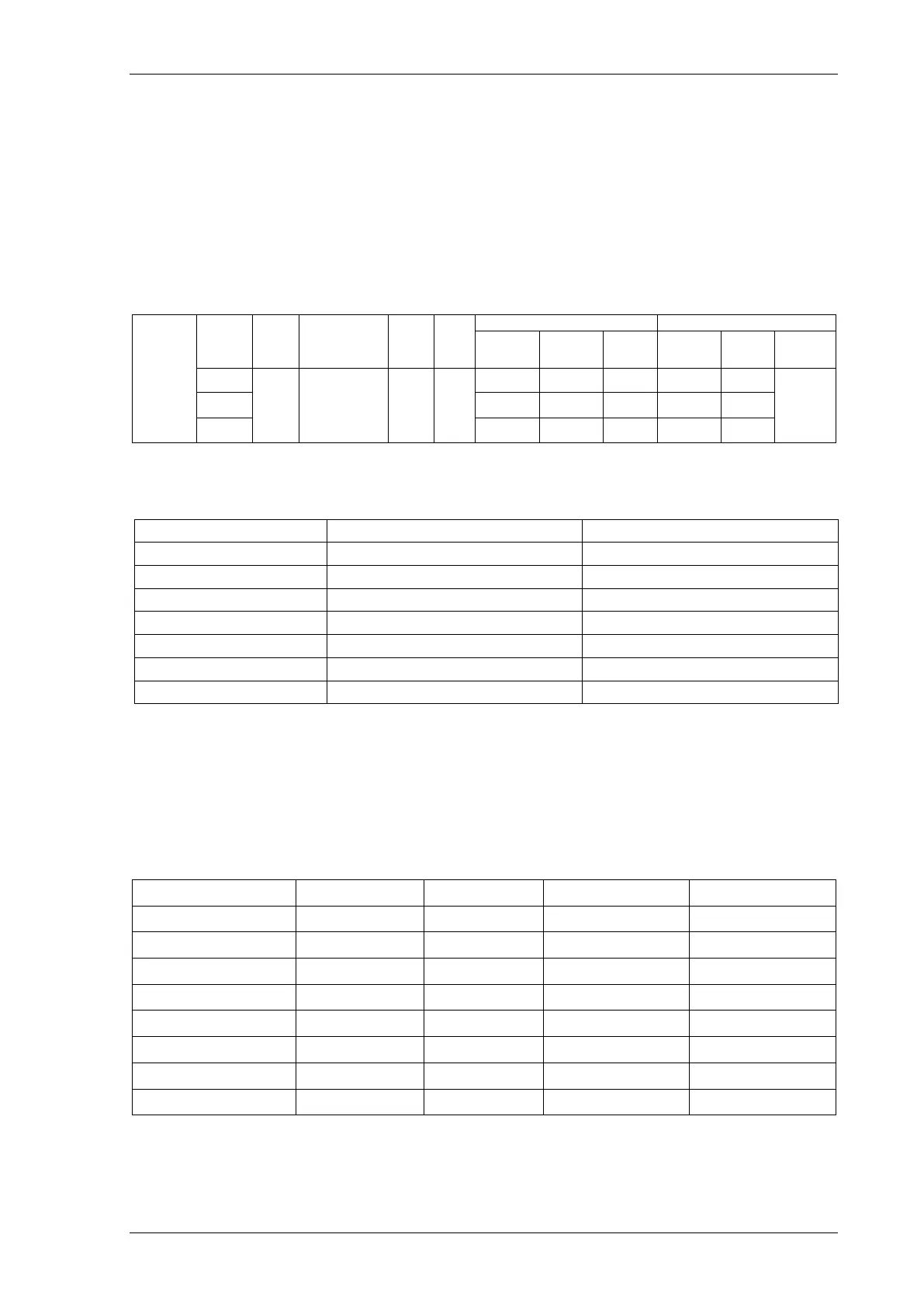
2.2.2 Inverse Time Overcurrent (51)
It will be advantageous to map the function being tested to temporarily drive the relevant Pickup output in the
Pickup Config sub-menu in the Output Config menu as this will allow the Pick-up led to operate for the function.
Gradually increase current until Pickup LED operates.
Apply 2x setting current and record operating time,
Apply 5x setting current and record operating time.
Compare to calculated values for operating times.
Gradually reduce current until the element drops off and record the level.
P.U.
D.O.
&
TIMIN
G
TESTS
Curve
(A)
(Amps)
(Amps)
(sec)
(sec)
L1
A
L2
B
L3
C
Calculated Timing values in seconds for TM =1.0
Curve 2 xIs 5 xIs
IEC-NI
10.03 4.28
IEC-VI
13.50 3.38
IEC-EI
26.67 3.33
IEC-LTI
120.00 30.00
3.80 1.69
ANSI-VI
7.03 1.31
ANSI-EI
9.52 1.30
Note that the operate time may be subject to the Minimum op time setting for the element and/or may have a
Follower DTL applied.
2.2.2.1 Element Blocking
The Phase Overcurrent elements can be blocked by Binary Input Inhibit, VT Supervision and Inrush Detector
operation, as well as 79 Autoreclose settings for Inst/Delayed. The Characteristic can be modified by Cold Load
(51-n only) and Voltage Controlled Overcurrent and can be made non-directional by VT Supervision. This
functionality should be checked.

 Loading...


