7SR11 & 7SR12 Description Of Operation
©2017 Siemens Protection Devices Limited Chapter 1 Page 45 of 88
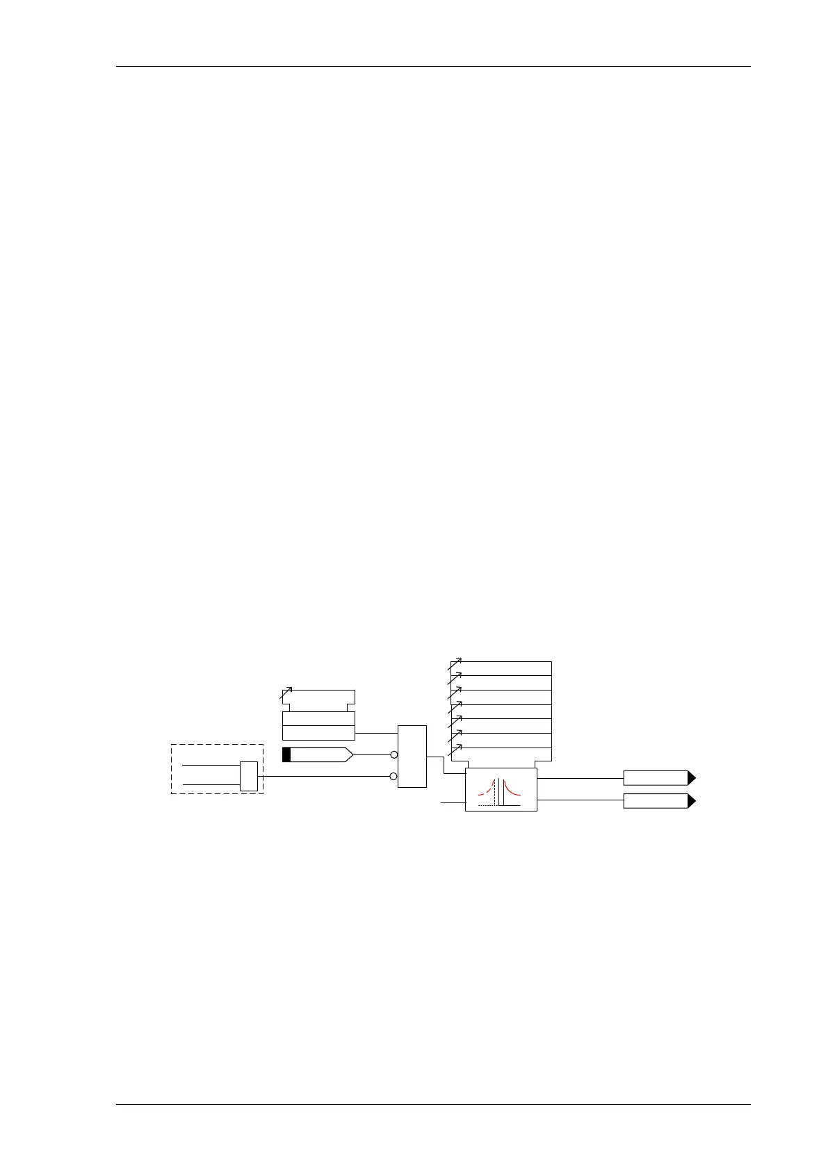
3.4.3 TIME DELAYED SENSITIVE EARTH FAULT PROTECTION (51SEF)
Two sensitive earth fault elements are provided in the 7SR11 relay and four elements are provided in the 7SR12
relay.
51SEF-1, 51SEF-2, (51SEF-3 & 51SEF-4– 7SR12)
51SEF-n Setting sets the pick-up current level.
A number of shaped characteristics are provided. An inverse definite minimum time (IDMT) characteristic is
selected from IEC and ANSI curves using 51SEF-n Char. A time multiplier is applied to the characteristic curves
using the 51SEF-n Time Mult setting. Alternatively, a definite time lag (DTL) can be chosen using 51SEF-n Char.
When DTL is selected the time multiplier is not applied and the 51SEF-n Delay (DTL) setting is used instead.
The 51SEF-n Reset setting can apply a definite time delayed reset, or when configured as an IEC or ANSI
characteristic an IEC/ANSI (DECAYING) reset. The reset mode is significant where the characteristic has reset
before issuing a trip output – see ‘Applications Guide’.
A minimum operate time for the characteristic can be set using 51SEF-n Min. Operate Time setting.
A fixed additional operate time can be added to the characteristic using 51SEF-n Follower DTL setting.
Where directional elements are present the direction of operation can be set using 51SEF-n Dir. Control setting.
Directional logic is provided independently for each 51SEF-n element e.g. giving the option of using two elements
set to forward and two to reverse.
Operation of the time delayed earth fault elements can be inhibited from:
Inhibit 51SEF-n A binary or virtual input
79 SEF Inst Trips: 51SEF-n When ‘delayed’ trips only are allowed in the auto-reclose sequence
(79 SEF Prot’n Trip n = Delayed).
51SEF-n VTSAction: Inhibit Operation of the VT Supervision function (7SR1205 & 7SR1206).
Directional elements will not operate unless the zero sequence voltage (V
0
) is above the 67SEF Minimum
Voltage setting i.e. the residual voltage is greater than 3 times this setting and the phase is in the
Forward/Reverse operating range. If 67SEF Wattmetric is set to Enabled, the calculated residual real power
must be above the 67SEF Wattmetric Power setting. The residual power P
res
is equal to the wattmetric
component of 3V
0
I
SEF
and therefore the wattmetric component of 9V
0
I
0
General Pickup
51SEF-n
51SEF-n Setting
51SEF-n Charact
51SEF-n Time Mult
51SEF-n Delay (DTL)
51SEF-n Follower DTL
51SEF-n Reset
51SEF-n Min Operate Time
c
Pickup
trip
I
4
(I
SEF
)
Inhibit 51SEF-n
&
51SEF-n Element
Enabled
Disabled
&
79 P/F Inst Trips
= 51SEF-n
79 P/F Prot’n Trip n
= Delayed
AUTORECLOSE
Figure 3-14 Logic Diagram: 7SR11 SEF Time Delayed Element (51SEF)

 Loading...


