7SR11 & 7SR12 Commissioning and Maintenance Guide
©2017 Siemens Protection Devices Limited Chapter 6 Page 60 of 72
Section 3: Supervision Functions
3.1 CB Fail (50BF)
7SR12
46
BC
46
NPS
(x2)
37
(x2)
49
50
BF
51V
V
L1
(V
A
)
V
L2
(V
B
)
V
L3
(V
C
)
I
L1
(I
A
)
81
HBL
2
37
(x2)
49
50
BF
51V
I
L2
(I
B
)
81
HBL
2
37
(x2)
49
50
BF
51V
I
L3
(I
C
)
81
HBL
2
I
4
(I
G
)
74
T/
CCS
NOTE: The use of some
functions are mutually exclusive
67/
50
(x4)
67/
51
(x4)
67/
50N
(x4)
67/
50
(x4)
67/
50
(x4)
67/
51
(x4)
67/
51
(x4)
67/
51N
(x4)
67/
50
SEF
67/
51
SEF
27
59
(x4)
27
59
(x4)
27
59
(x4)
47
(x2)
81
(x6)
79
Optional
59
N
(x2)
Note:
Example shows
Voltage Config =
Van, Vbn, Vcn
60
CTS
60
VTS
50
BF
51c
51c
51c
64H
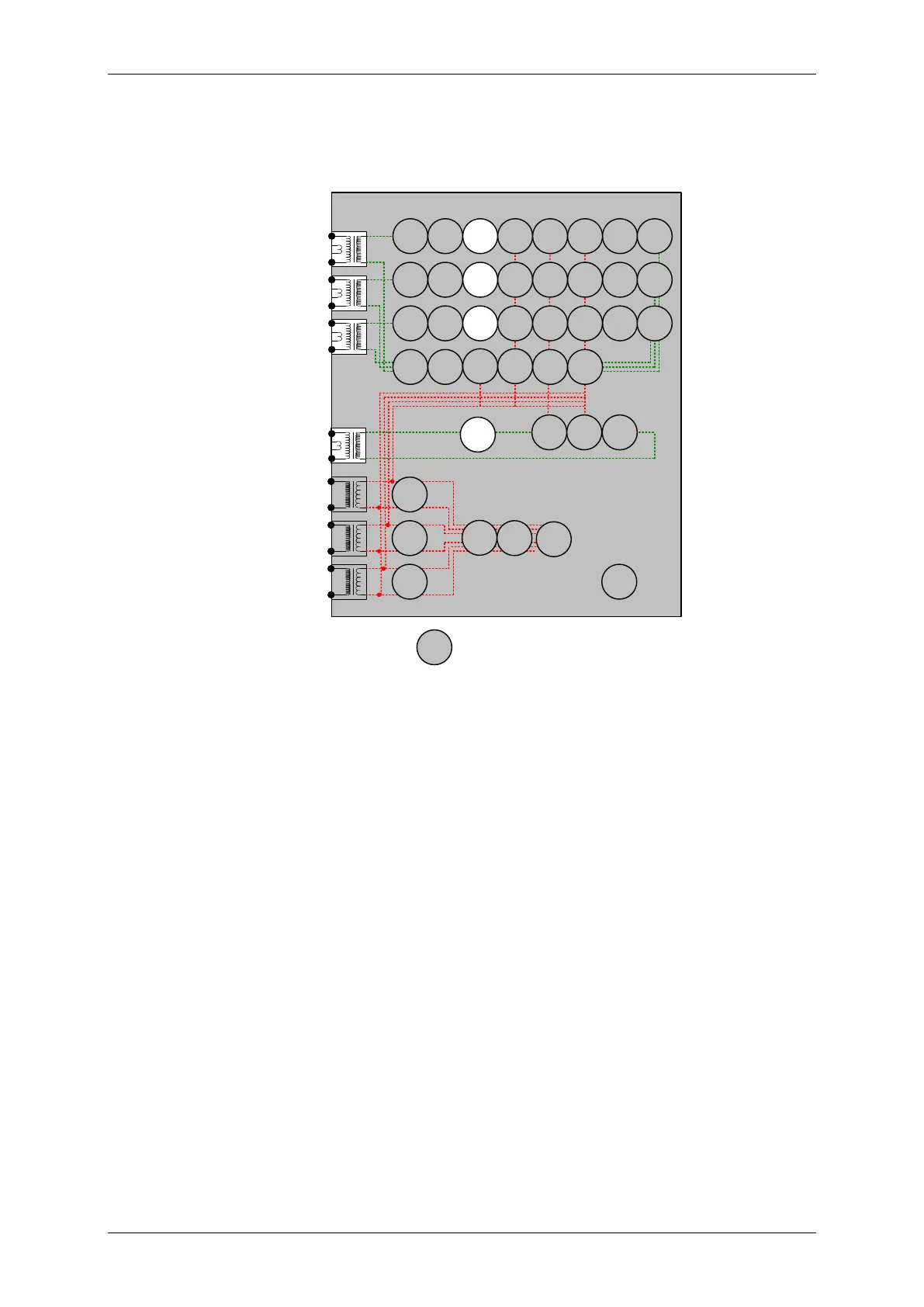
Figure 2-22 CB Fail
Voltage Inputs: n/a
Current Inputs: I
L1
(I
A
), I
L2
(I
B
), I
L3
(I
C
), I
L4
Disable:
Map Pickup LED: 50BF-n - Self Reset
The circuit breaker fail protection time delays are initiated either from:
A binary output mapped as Trip Contact in the OUTPUT CONFIG>BINARY OUTPUT CONFIG menu,
or
A binary input mapped as 50BF Ext Trip in the INPUT CONFIG>INPUT MATRIX menu.
Or
A binary input mapped as 50BF Mech Trip in the INPUT CONFIG>INPUT MATRIX menu.
Apply a trip condition by injection of current to cause operation of a suitable protection element. Allow current to
continue after the trip at a level of 110% of the 50BF Setting current level on any phase. Measure the time for
operation of 50BF-1 Delay and 50BF-2 Delay. Repeat the sequence with the 50BF CB Faulty input energised and
ensure the 50BF-1 and 50BF-2 outputs operate without delay, by-passing the timer delay settings.
Repeat the sequence with current at 90% of the 50BF Setting current level after the element trip and check for no
CB Fail operation.
Repeat the sequence by injecting the current to I4 and using the 50BF-I4 Setting.

 Loading...


