7SR11 & 7SR12 Commissioning and Maintenance Guide
©2017 Siemens Protection Devices Limited Chapter 6 Page 11 of 72
Section 2: Protection Functions
This section details the procedures for testing each protection function of the 7SR11 & 7SR12 relays. These tests
are carried out to verify the accuracy of the protection pick-ups and time delays at setting and to confirm correct
operation of any associated input and output functionality.
The exact model type must be checked to confirm the functions available in each type.
Guidance for calculating test input quantities is given in the relevant test description where required. In many
cases it may be necessary to disable some functions during the testing of other functions, this prevents any
ambiguity caused by the operation of multiple functions from one set of input quantities. The ‘Function Config’
Menu provides a convenient high level point at which all elements of a particular function can be
Enabled/Disabled to suit testing. The ‘Config’ tab in ‘Reydisp Evolution’ can be used to ‘Enable/Disable’ individual
elements. Note that this screen disables functions by applying setting changes to the relay and that any changes
must be sent to the relay to take effect and settings must be returned to their correct value after testing.
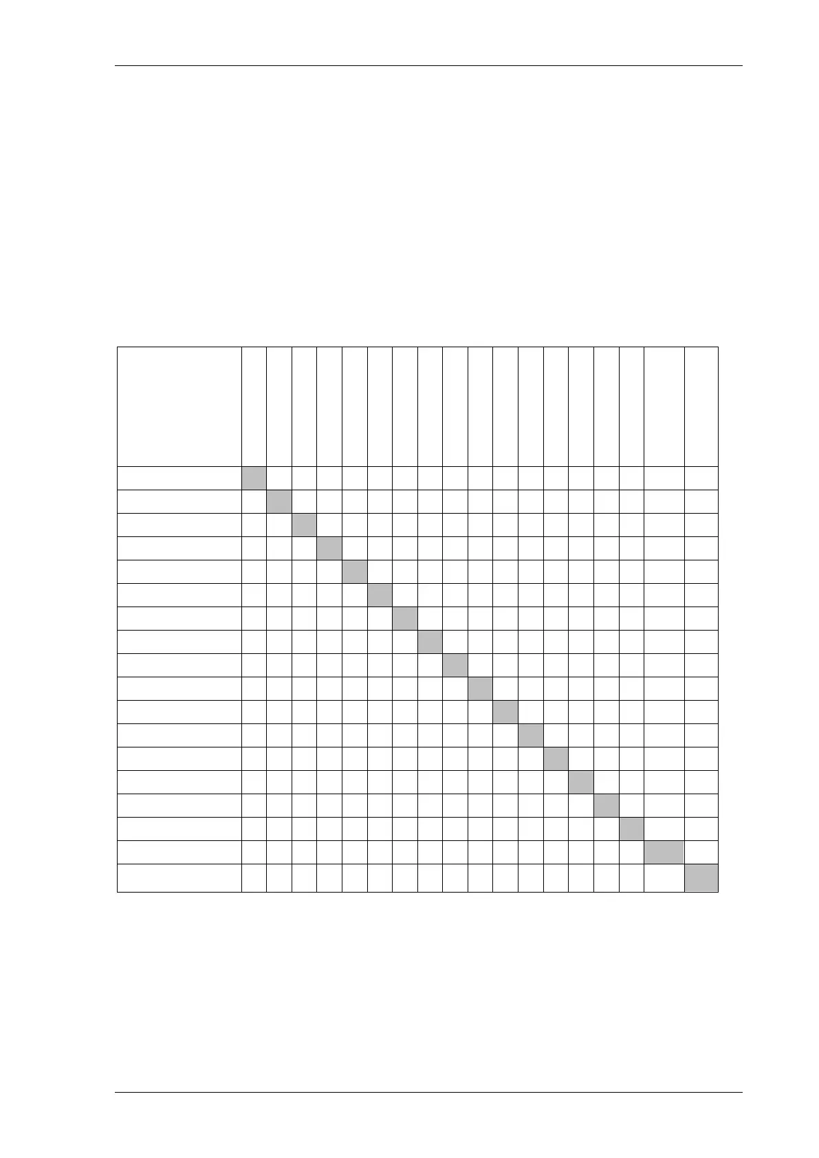
The table below indicates functions where function conflicts may occur during testing, consideration should be
given to disabling functions to avoid interference.
Any LED can be assigned to be a General Pickup LED in the Output Matrix menu and used to assess operation
of functions during testing if other functions are disabled or if the setting allocating General Pickup is temporarily
modified.
Voltage inputs may not be required for testing of non-directional Overcurrent elements but it may be
advantageous to apply balanced 3 phase nominal rated voltage to the VT inputs during testing to avoid
inadvertent operation of other functions. Particular care should be taken when testing overcurrent functions that
the thermal rating of the current inputs is not exceeded.
Function
Under Test
Cold Load
Sensitive E/F
Thermal
CB Fail
Trip cct
Supervision
Inrush Detector
Voltage Cont O/C
O
O O O O O O
Derived E/F
O O O O O O O
Measured E/F
O
O O O
NPS Overcurrent
O O O
O O O O
Phase U/O voltage
O O O
CB Fail
O O O O O O O O
VT Supervision
O O
Trip cct
Inrush Detector

 Loading...


