7SR11 & 7SR12 Commissioning and Maintenance Guide
©2017 Siemens Protection Devices Limited Chapter 6 Page 50 of 72
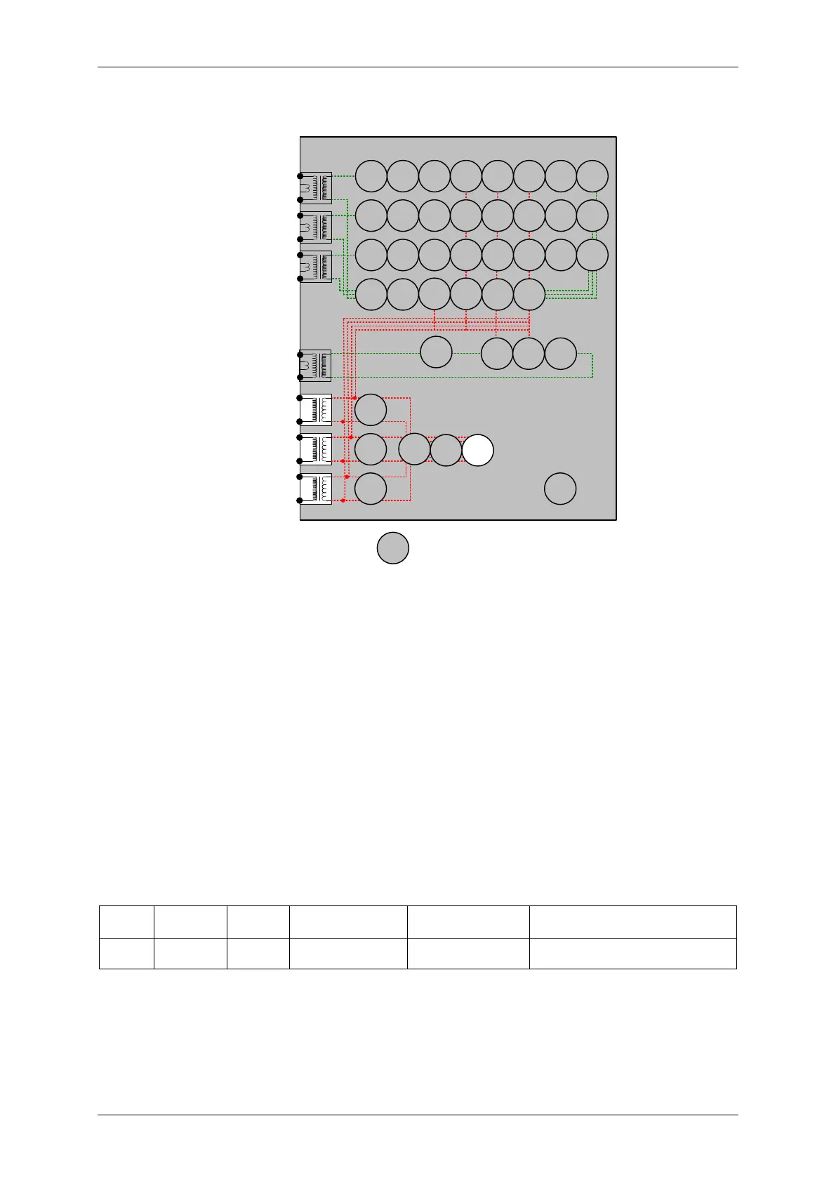
2.14.5 Neutral Overvoltage (59N)
7SR12
46
BC
46
NPS
(x2)
37
(x2)
49
50
BF
51V
V
L1
(V
A
)
V
L2
(V
B
)
V
L3
(V
C
)
I
L1
(I
A
)
81
HBL
2
37
(x2)
49
50
BF
51V
I
L2
(I
B
)
81
HBL
2
37
(x2)
49
50
BF
51V
I
L3
(I
C
)
81
HBL
2
I
4
(I
G
)
74
T/
CCS
NOTE: The use of some
functions are mutually exclusive
67/
50
(x4)
67/
51
(x4)
67/
50N
(x4)
67/
50
(x4)
67/
50
(x4)
67/
51
(x4)
67/
51
(x4)
67/
51N
(x4)
67/
50
SEF
67/
51
SEF
27
59
(x4)
27
59
(x4)
27
59
(x4)
47
(x2)
79
Optional
59N
(x2)
Note:
Example shows
Voltage Config =
Van, Vbn, Vcn
60
CTS
60
VTS
50BF
51c
51c
51c
64H
81
(x4)
Figure 2-17 Neutral Overvoltage
Voltage Inputs: V
L1
(V
A
), V
L2
(V
B
), V
L3
(V
C
)
Current Inputs: n/a apply zero current to stabilize other functions
Disable: 27/59, 47, 60VTS
Map Pickup LED: 59N-n - Self Reset
The voltage source for the Neutral Overvoltage 59N function is Vn, calculated from the applied 3 phase voltage
inputs. To test, apply test voltage to one phase input.
2.14.6 Definite Time (59NDT)
If DTL setting is small, gradually increase single phase voltage until element operates.
If DTL is large apply 0.9x setting, check for no operation, apply 1.1x setting, check operation
Apply 2x setting voltage if possible and record operating time
(Volts)
(sec)
(Volts)
@ 2 x Vs
Check correct indication, trip output, alarm contacts, waveform record.
2.14.7 Inverse Time (59NIT)
It will be advantageous to map the function being tested to temporarily drive the relevant Pickup output in the
Pickup Config sub-menu in the Output Config menu as this will allow the Pick-up led to operate for the function.

 Loading...


