7SR11 & 7SR12 Description Of Operation
©2017 Siemens Protection Devices Limited Chapter 1 Page 41 of 88
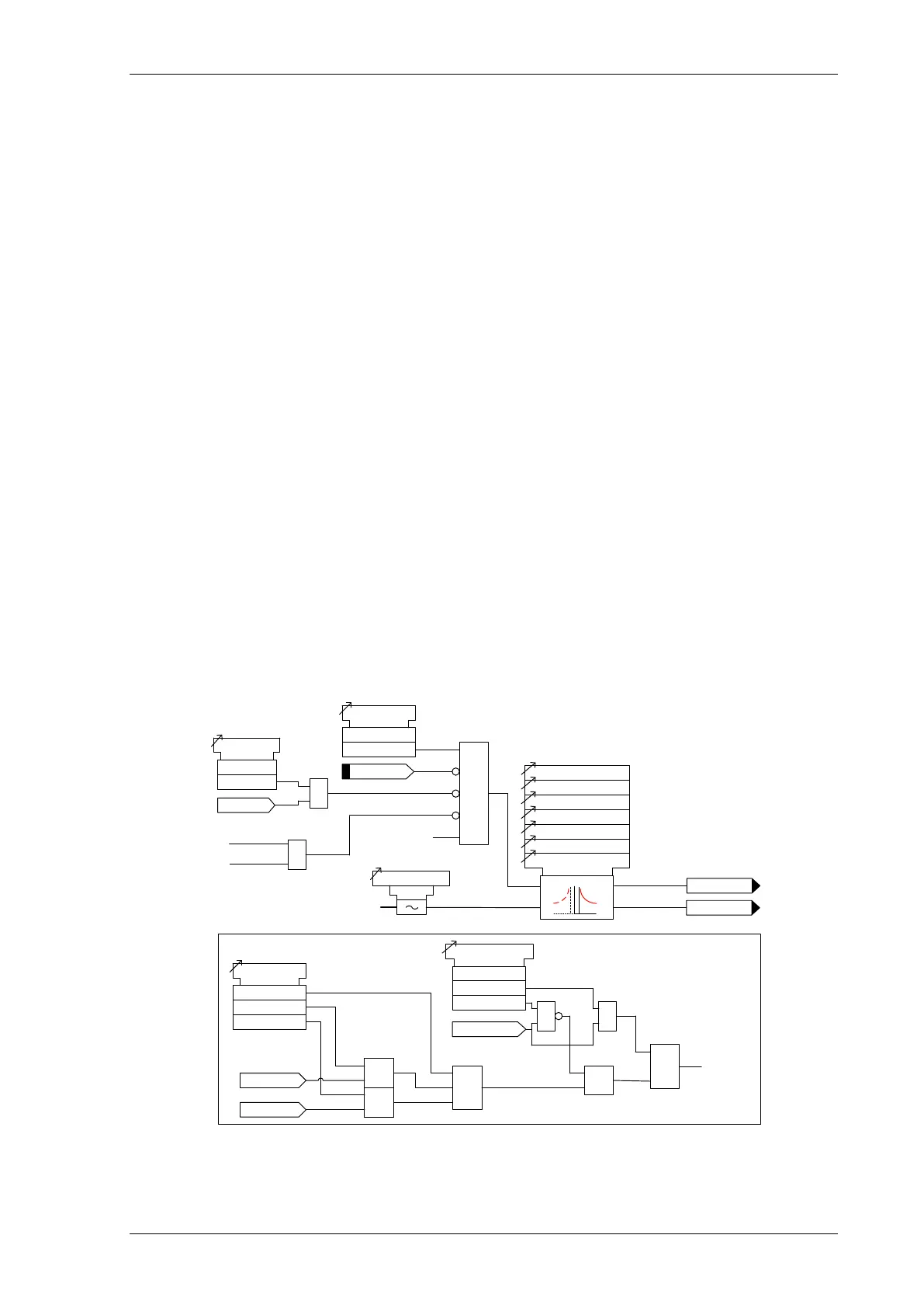
3.3.3 TIME DELAYED MEASURED EARTH FAULT PROTECTION (51G)
Two instantaneous derived earth fault elements are provided in the 7SR11 relay and four elements are provided
in the 7SR12 relay.
51G-1, 51G-2, (51G-3 & 51G-4 – 7SR12)
51G-n Setting sets the pick-up current level.
A number of shaped characteristics are provided. An inverse definite minimum time (IDMT) characteristic is
selected from IEC and ANSI curves using 51G-n Char. A time multiplier is applied to the characteristic curves
using the 51G-n Time Mult setting. Alternatively, a definite time lag (DTL) can be chosen using 51G-n Char.
When DTL is selected the time multiplier is not applied and the 51G-n Delay (DTL) setting is used instead. The
full list of operating curves is given in Section 2 – ‘Settings, Configuration and Instruments Guide’. Operating
curve characteristics are illustrated in Section 3 – ‘Performance Specification’.
The 51-n Reset setting can apply a definite time delayed reset, or when the operation is configured as an IEC or
ANSI or user characteristic if the reset is selected as IEC/ANSI (DECAYING) reset the associated reset curve will
be used. The reset mode is significant where the characteristic has reset before issuing a trip output – see
‘Applications Guide’
A minimum operate time for the characteristic can be set using 51G-n Min. Operate Time setting.
A fixed additional operate time can be added to the characteristic using 51G-n Follower DTL setting.
Where directional elements are present the direction of operation can be set using 51G-n Dir. Control setting.
Directional logic is provided independently for each 51G-n element e.g. giving the option of using two elements
set to forward and two to reverse.
Operation of the time delayed measured earth fault elements can be inhibited from:
Inhibit 51G-n A binary or virtual input.
79 E/F Inst Trips: 51G-n When ‘delayed’ trips only are allowed in the auto-reclose sequence
(79 E/F Prot’n Trip n = Delayed).
50-n Inrush Action: Block Operation of the inrush current detector function.
51G-n VTSAction: Inhibit Operation of the VT Supervision function (7SR1205 & 7SR1206).
General Pickup
51G-n
If directional elements are not present this block is
omitted and the '50G-n Dir En' signal is set TRUE.
Forward
Reverse
51G-n Dir
Non-Dir
≥1
&
&
51G-n Dir En
67G Fwd
67G Rev
51G-n VTS Action
Off
Non Dir
Inhibit
VT Fail
& &
&
≥1
I
4
(I
G
)
51G/50G Measurement
51G-n Setting
51G-n Charact
51G-n Time Mult
51G-n Min Operate Time
51G-n Reset
51G-n Delay (DTL)
51G-n Follower DTL
c
Pickup
trip
Inhibit 51G-n
&
51G-n Element
Enabled
Disabled
81HBL2
51G-n Inrush
Action
Off
Inhibit
&
51G-n Dir En
&
79 P/F Inst Trips
= 51G-n
79 P/F Prot’n Trip n
= Delayed
AUTORECLOSE
Figure 3-10 Logic Diagram: Measured Time Delayed Earth Fault Element (51G)

 Loading...


